03217917-01-01E By DEK Technical Reference Manual Vol 1_enPDFA.pdf - 第288页
17 CAMERA SYSTEM MODULE 17.5 CALIBRATIONS AND CHECKS 288 TECHNICAL REFERENCE MANUAL Vol 1 E By DEK 04/2019 17.5.2.4 Associated Calibrations Camera Replacement - Calibrations Required (Y/N) Motor Replacement - Calibration…

17 CAMERA SYSTEM MODULE
17.5 CALIBRATIONS AND CHECKS
TECHNICAL REFERENCE MANUAL Vol 1 E By DEK 04/2019 287
17.5.2.3 Stage 2 - Calibrate Offset
► Select Offset.
► Select Setup OK.
► Place the calibration board, with the fiducials downward facing, onto the upline conveyor.
► Select Auto Board, the board moves to the board stop position.
► Select Step, the board is clamped and the board stop retracts.
► Select Step, the camera moves to the first stencil fiducial and the squeegee moves to dwell
height.
► Using the Incr. and Decr. buttons, position the stencil fiducial (right hand image) so that it is
placed centrally with the box displayed.
► Select Step, the camera moves to the second stencil fiducial. Position the fiducial centrally
within the box as previously described.
► Select Step, the camera moves to the third stencil fiducial. Position the fiducial centrally within
the box as previously described.
► Select Step, the camera returns to the home position and the rising table moves to the print
height position.
► Select Step, the print carriage moves to the rear position.
► Open the printhead cover.
► Apply paste to all 25 positions on the stencil.
► Close the printhead cover.
► Press the System button.
► Select Step.
► Select Step.
► Select Accept, the table drops and the camera moves to the first fiducial.
► Select Brd Fid Setup using a combination of the Incr. or Decr. and Next. and Previous. but-
tons centre the fiducial set the background to light and the diameter to 1.00mm.
► Select Learn Fiducial.
► Using a combination of the Incr. or Decr. and Next. and Previous. buttons centre the fiducial.
► Select Learn Fiducial.
► Select Exit.
► Select Locate Fiducial.
► Select Exit.
► Select Exit.
► Select Scrn Fid Setup.
► Select Locate Fiducial.
► Select Exit.
► Select Exit.
► Select Step, the offset results are displayed.
► Select Single, the camera moves to each of the 24 remaining fiducial positions in turn.
► Select Auto Board, the board data file is saved.
► Remove the board from the transport rails.
► Select Exit.
► Select Back.
► Select Back.
17 CAMERA SYSTEM MODULE
17.5 CALIBRATIONS AND CHECKS
288 TECHNICAL REFERENCE MANUAL Vol 1 E By DEK 04/2019
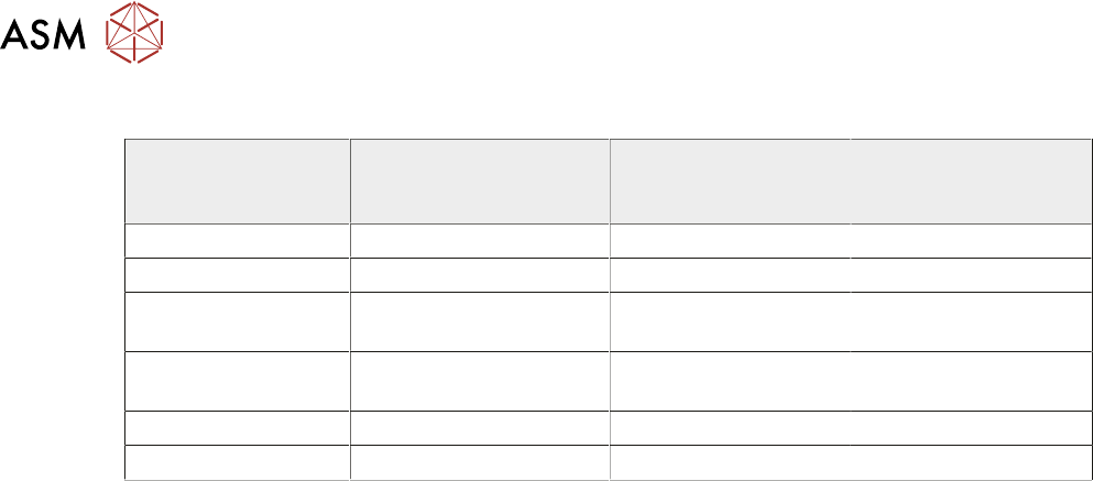
17.5.2.4 Associated Calibrations
Camera Replacement -
Calibrations Required
(Y/N)
Motor Replacement -
Calibrations Re-
quired (Y/N)
Belt Replacement -
Calibrations Re-
quired (Y/N)
Vision Height Y N N
Belt Tension N N Y
X Axis to Front Rail
Parallelism
N N Y
Camera Reference
Position
Y Y Y
Vision Calibration Y Y Y
Offset Calibration Y Y Y

17 CAMERA SYSTEM MODULE
17.6 APPENDIX A - VISION SYSTEM SETUP
TECHNICAL REFERENCE MANUAL Vol 1 E By DEK 04/2019 289
17.6 APPENDIX A - VISION SYSTEM SETUP
17.6.1 Preparing the Vision System
The following procedure is typical for all fiducial shapes, although in this procedure a circle fiducial
shape is referred to throughout.
► Select Setup Product.
► Select Fiducials.
► Select Load Board.
► Place a board on the input side of the rails.
► Select Auto Board.
► Select Fiducial Setup.
► Select the board or stencil fiducial that requires setting up from the control buttons on the left.
► Select Shape to change the fiducial type. The options are:
●
Circle
●
Rectangle
●
Diamond
●
Cross
●
Video Model
NOTE
Video Model allows a unique feature to be used instead of a standard fiducial shape.
► Select Width to change the overall width of the fiducial.
► Select Board Fiducial # /X Board Fiducial # Y to change the location of the fiducial in the X
and Y directions. The dimension is measured from the left hand side edge of the board to the
centre of the fiducial.
► Select Fiducial Inner Contour/Fiducial Outer Contour to setup the area within the fiducial
to be ignored by the vision system.
► Select Accept Score to setup the level as to whether a found fiducial should be accepted or
rejected.
► Select Background to select whether the area surrounding the fiducial is lighter or darker in
comparison to the fiducial colour.
► Select the Lighting tab.
► Adjust the lighting parameters to a level whereby the fiducials just ‘white out’, without bloom-
ing. Default level 8 on both Vertical and Oblique is usually adequate for the majority of fidu-
cials.
► Select the Manual Setup tab.
► Select Learn and Locate.
A table appears on the monitor indicating the score of the fit between the synthetic fiducial and the
actual fiducial. The synthetic fiducial parameters may need resetting and re-learning to obtain a
better figure if there are other features in the camera window.
► Select Continue.
► Select Locate.
► Select Continue.
► Repeat select Shape process for other fiducials that require setting up.
► Select Exit.
► Select Unload Board.
► Select Auto Board.
► Select Back.
► Select Save.