00198605-01_AI_EbS_SST25_Camera_EN.pdf - 第7页
1 Introduction 1.2 Preparatory Work... Assembly Instructions E by SIPLACE SST25 Camera Option 03/2018 7 1.1.4 Safety Instructions for the Gantry CAUTION Moving the gantry can damage the placement head. When moving the ga…
1 Introduction
1.1 Safety Instructions
6 Assembly Instructions E by SIPLACE SST25 Camera Option 03/2018
1.1.2 Safety Instructions for Working with Strong Magnetic Fields
DANGER
Strong permanent magnetic fields
Fatal hazard: persons with active implants (e.g. pacemakers, defibrillators, insulin pumps,
etc.) are at risk from strong permanent magnetic fields inside the machine.
Persons at risk should avoid the immediate vicinity of the machine.
CAUTION
Danger of crushing
Danger of crushing for persons with passive metal implants (e.g. plates, screws).
► Do not reach or lean over into the machine when the covers are open.
► Do not bring any metal objects into the danger area.
CAUTION
Strong permanent magnetic fields
There is a risk that the strong magnetic fields could corrupt data on data media or check
cards.
► Keep sensitive data supports away from the permanent magnets.
1.1.3 Safety Instructions for the Power Supply
DANGER
Hazardous Voltages!
The machine is supplied with 3x400V~ (or 3x204V~ / 3 x 220V~ / 3 x 230V~ / 3 x
380V~ / 3x415V~) ± 5%, 50/60Hz mains voltages.
► Observe the safety instructions in the user manual during all service work!
► Before you start working on the power supply, check it for absence of voltage and ob-
serve the waiting times!
●
This means that some parts of the system carry potentially lethal voltages - even when
switched off at the main power switch.
●
Incorrect handling of the placement system can therefore result in fatal injuries, severe injuries
or considerable damage to equipment.
●
Measurements and maintenance work must always be carried out by appropriately qualified
personnel.
●
Always follow the applicable accident prevention and DIN regulations (particularly DIN EN 60
204, part 1) or the regulations specific to your country.
●
Before starting any maintenance work, switch the machine off at the main switch and discon-
nect it from the main power supply.
●
Always secure the machine against unauthorized reactivation. If these instructions are not fol-
lowed, you may be able to touch live parts, which could result in fatal or severe injuries.
Maintaining, installing or removing assemblies
► End all placement operations on the machine.
► Shut down the Windows operating system correctly, otherwise problems may occur when re-
starting the system or data may be lost.
► Switch off the machine at the main switch.
► Disconnect the machine from the main power supply.
► Switch off the machine and attach warning signs to indicate that service work is in progress.
1 Introduction
1.2 Preparatory Work...
Assembly Instructions E by SIPLACE SST25 Camera Option 03/2018 7
1.1.4 Safety Instructions for the Gantry
CAUTION
Moving the gantry can damage the placement head.
When moving the gantry, observe the following:
► NEVER move the gantry by pushing with your hands against the placement head.
► NEVER push the gantry while the Z axis is lowered.
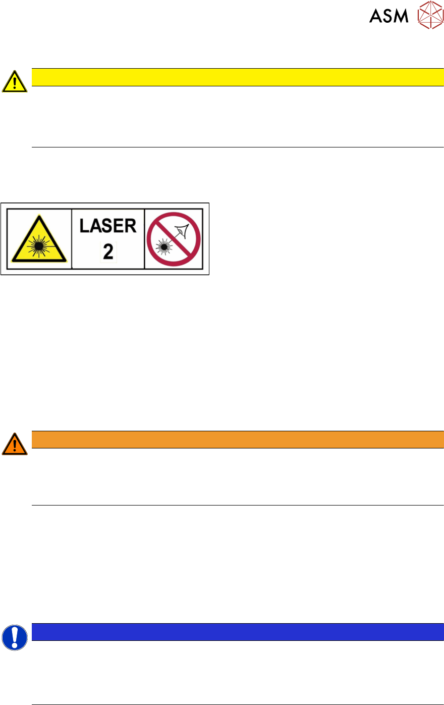
1.1.5 Classification of the Optical Systems
1.1.5.1 Classification of the Whole Machine
Fig.1: Laser class 2
The ready-to-operate overall machine is assigned
to laser class°2.
The laser classes are determined according to
DIN EN 60825-1:2014.
1.1.5.2 Laser Classification
The following modules are assigned to laser class 2:
●
ICR850 series PCB barcode scanner
●
Component sensor on the SpeedStar
●
Component sensor on the MultiStar
●
Laser light barriers at the board conveyor
1.1.5.3 Classification of the Camera Systems
WARNING
LEDs
The camera illumination systems are fitted with light LEDs. These are assigned to risk
group 1 according to IEC 62741:2006.
► Do not look into beam!
1.2 Preparatory Work...
Purpose and Scope
Before performing any preventive maintenance work, conversion work or service work, a procedure
of locking and tagging must be followed and warning signs must be attached if not stated other-
wise. If it is not necessary to switch off the machine, it is explicitly mentioned.
The procedure, when followed correctly, eliminates the possibility of an employee being injured.
NOTICE
Additional safety measures
These procedures represent the minimum lock/tag out requirements for the machine during
preventive maintenance work and service work. Any additional safeguards needed to com-
plete work safely can be specified by facilities supervision, the safety officer, the safety
committee and the health department.
1 Introduction
1.2 Preparatory Work...
8 Assembly Instructions E by SIPLACE SST25 Camera Option 03/2018
Description
Whenever it becomes necessary to isolate, control and release energy, the following procedure is
to be followed.
► Notify affected employees.
► Switch off the machine and all additional devices. Carry out all normal stopping procedures:
ð Press the STOP button.
ð Shut down the station computer.
ð Switch the machine off at the main switch.
► Isolate the machine from all its energy sources:
ð Shut off the compressed air supply.
ð Shut off the main power supply.
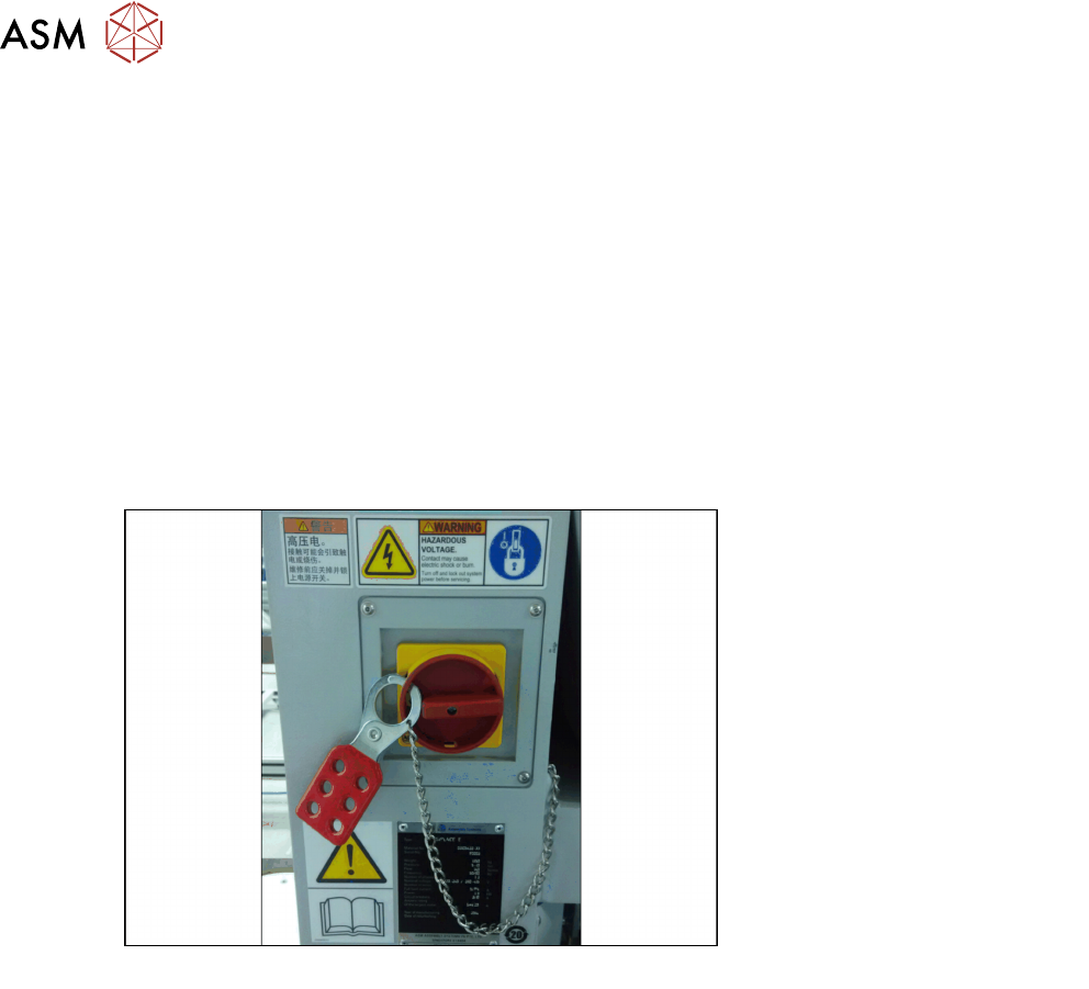
► Lock out the machine.
ð Attach a lock wherever possible (e.g. to the main power switch or the motor contactor).
Fig.2: Lock on main power switch
Example
► Alternative: attaching warning signs
If a machine can be locked, it must be. However, there are situations where energy isolating
devices cannot accommodate locks. In these cases, the energy isolating devices must be
tagged to warn employees that the machine is de-energized for servicing. The tag or label
must be securely fastened, it must be placed in a position visible to all and it may only be re-
moved by the person who attached it.
► Release of stored energy:
Stored energy in the compressed air supply or electrical energy in electrolytic capacitors must
be released by appropriate means.
ð After switching off the machine, wait until the voltages and the compressed air have dis-
charged, so that work can be performed without any risk.
► Testing the lock out:
The lock can be easily tested by pressing the START button.
► The following steps must be taken to restore the machine to operation.
► Check the working area. Authorized employees should remove all of their tools and reinstall
all safety features.
► Notify all affected employees.
► Before removing even one lock or tag, inform all workers in the affected area that the machine
is going to be restarted.
► Remove locks/tags
► Every authorized employee must remove his own lock and shut it away.
► Turn the machine on. Make sure that authorized staff check the equipment in operation to en-
sure that repairs were performed correctly