plug-play-alep-automatic-feed-soldering-jbc-0037587_ID-269348_EN.pdf - 第3页
EAR TH FUSE F1.25 A USE ONL Y WITH A 250 V FUSE EAR TH FUSE F1.25 A 1 2 3 5 4 3 40 mm 50 mm 60 mm 80 mm 100 mm 130 mm 130 mm par a manuales - neg r o plano 200 mm 300 mm Step 1 Solder Reel Assembly Reel L ocking Solder W…
2
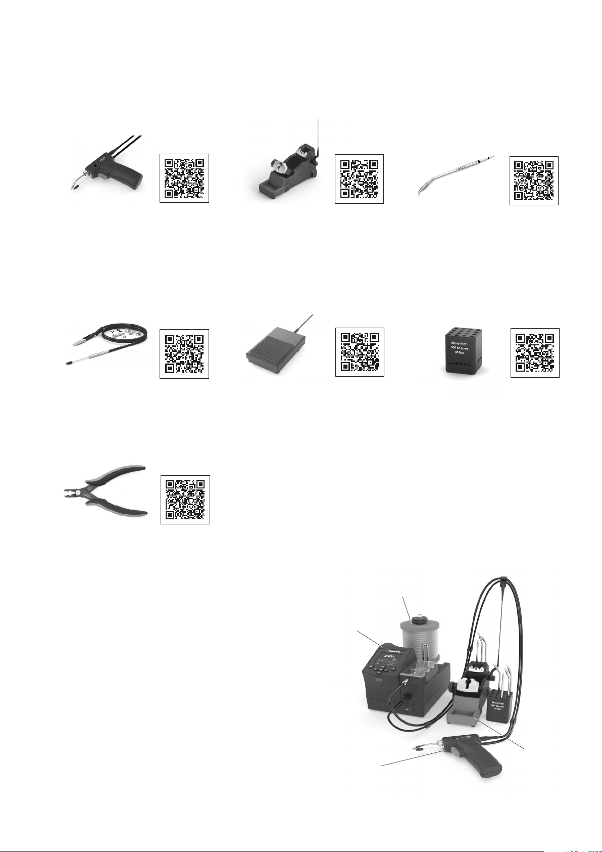
The following items are included:
Angled Automatic-Feed
Soldering Iron ................................. 1 unit
Ref. ALEP250-A
Pedal ............................................... 1 unit
Ref. P-405
Solder Wire Guide Kit ..................... 1 unit
According to purchased station reference.
Cartridge Holder ............................. 1 unit
Ref. SCH-A
Stand for ALE250-A and ALEP250-A
Automatic-Feed Soldering Iron ...... 1 unit
Ref. ALE-SA
Conical Bent Cartridge Ø 1 ............ 1 unit
Ref. C250403
Cartridge Extractor Pliers ............... 1 unit
Ref. PLR196
Packing List
Installation
Before you can start working, follow the assembly steps in this P&P
Guide.
Note: The solder diameter must match the ALE model purchased.
Make sure the solder wire diameter is compatible with the wheels
already installed in the ALE control unit.
*Solder reel is not included.
Wheels (inside)
Solder Reel *
Tool Stand
Soldering Iron
EARTH FUSE F1.25 A
USE ONLY WITH A 250 V FUSE
EARTH FUSE F1.25 A
1
2
3
5
4
3
40 mm
50 mm
60 mm
80 mm
100 mm
130 mm
130 mm
para manuales - negro plano
200 mm
300 mm
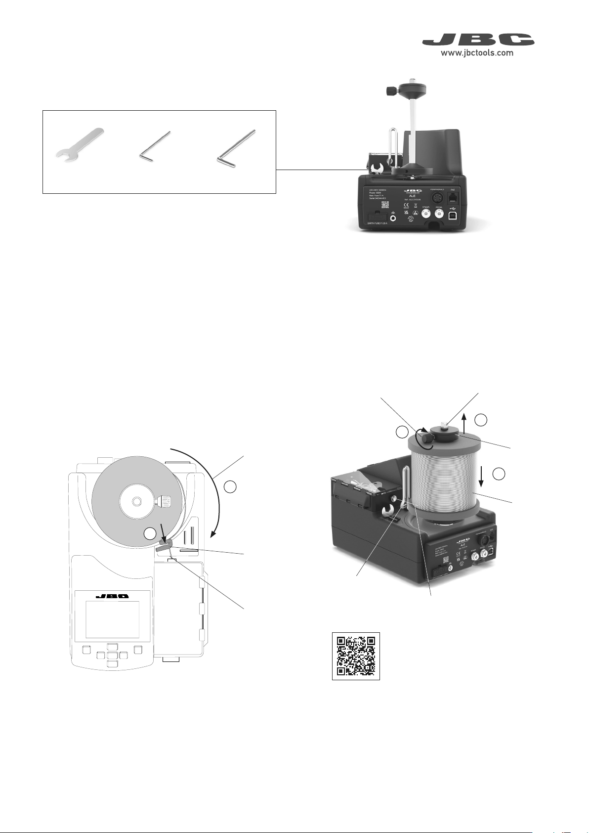
Step 1 Solder Reel Assembly
Reel Locking
Solder Wire
Guidance
Solder Wire
Axis
Solder Reel
Reel Locking
Screw
Solder Wire
Solder Wire
Unwinding
Direction
Solder Wire
Guidance
Loosen the reel locking screw (1) and remove the reel locking from
the axis (2).
Assemble the solder reel onto the axis (3).
Assemble the solder reel in such a way - when viewed from above -
that the solder wire unwinds on the dispensing mechanism side (4).
Then pass the solder wire through the wire guidance (5).
The required tools are located on the control unit.
Tools Needed
Allen Key Ø 2.5Allen Key Ø 1.5
Spanner
Watch the
product
assembly video
EARTH FUSE F1.25 A
USE ONLY WITH A 250 V FUSE
EARTH FUSE F1.25 A
EARTH FUSE F1.25 A
USE ONLY WITH A 250 V FUSE
EARTH FUSE F1.25 A
EARTH FUSE F1.25 A
USE ONLY WITH A 250 V FUSE
EARTH FUSE F1.25 A
EARTH FUSE F1.25 A
USE ONLY WITH A 250 V FUSE
EARTH FUSE F1.25 A
3
1
4
5
3
3
1
2
2
3
4
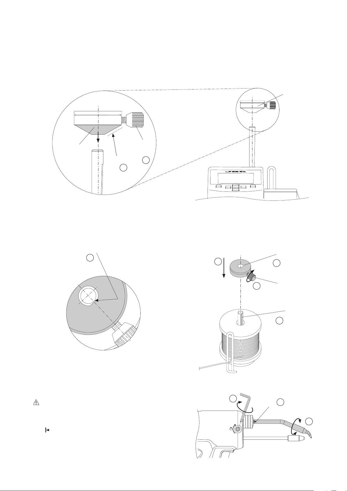
Mark
Step 3 Cartridge Assembly
For a safe cartridge assembly/change, make sure that the tool is
unplugged and the cartridge has cooled down.
Loosen the cartridge set screw (1) and insert the cartidge up to its
mark (2). Important: It is essential to insert the cartridge completely
for a good connection.
Adjust the tip direction (3) and tighten the cartridge set screw (1).
Top View
of the Reel Locking
Flat Side
(Reel Locking and Axis)
Reel Locking
Screw
Flat Side
of the Axis
Flat Side of the
Reel Locking
Step 2 Reel Locking Assembly
Reel Locking
Reel Locking
Conical
Side
To assemble the reel locking, its conical side must be pointing
downwards (1).
Make sure that the reel locking screw is slightly backed out and does
not collide with the axis (2).
Align the flat side of the axis with the inner flat side of the reel locking
(3) and assemble the reel locking to the axis (4).
Note: To prevent the solder reel from spinning freely or binding, gently
press the reel locking down, but only enough to allow the solder reel
to rotate freely, before tightening the reel locking screw (5).
Reel Locking
Screw