plug-play-alep-automatic-feed-soldering-jbc-0037587_ID-269348_EN.pdf - 第4页
EAR TH FUSE F1.25 A USE ONL Y WITH A 250 V FUSE EAR TH FUSE F1.25 A EAR TH FUSE F1.25 A USE ONL Y WITH A 250 V FUSE EAR TH FUSE F1.25 A EAR TH FUSE F1.25 A USE ONL Y WITH A 250 V FUSE EAR TH FUSE F1.25 A EAR TH FUSE F1.2…
EARTH FUSE F1.25 A
USE ONLY WITH A 250 V FUSE
EARTH FUSE F1.25 A
1
2
3
5
4
3
40 mm
50 mm
60 mm
80 mm
100 mm
130 mm
130 mm
para manuales - negro plano
200 mm
300 mm
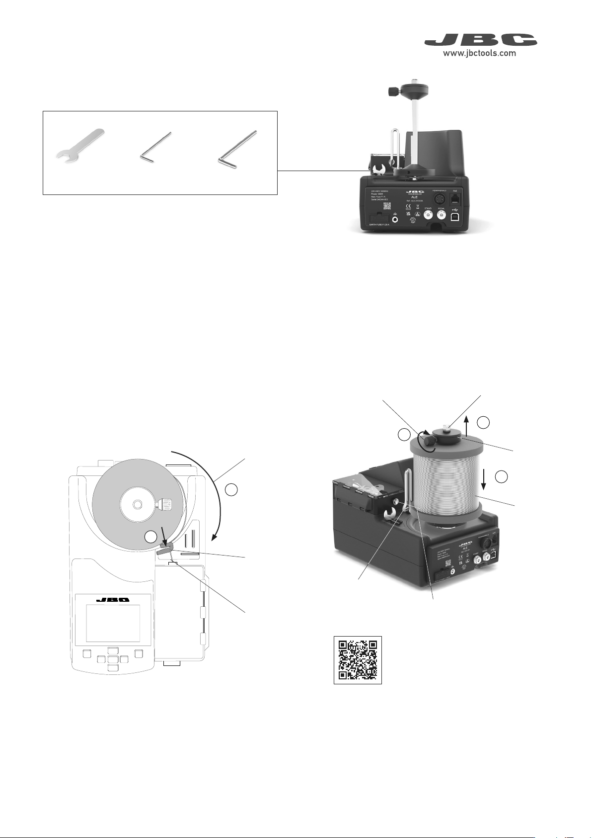
Step 1 Solder Reel Assembly
Reel Locking
Solder Wire
Guidance
Solder Wire
Axis
Solder Reel
Reel Locking
Screw
Solder Wire
Solder Wire
Unwinding
Direction
Solder Wire
Guidance
Loosen the reel locking screw (1) and remove the reel locking from
the axis (2).
Assemble the solder reel onto the axis (3).
Assemble the solder reel in such a way - when viewed from above -
that the solder wire unwinds on the dispensing mechanism side (4).
Then pass the solder wire through the wire guidance (5).
The required tools are located on the control unit.
Tools Needed
Allen Key Ø 2.5Allen Key Ø 1.5
Spanner
Watch the
product
assembly video
EARTH FUSE F1.25 A
USE ONLY WITH A 250 V FUSE
EARTH FUSE F1.25 A
EARTH FUSE F1.25 A
USE ONLY WITH A 250 V FUSE
EARTH FUSE F1.25 A
EARTH FUSE F1.25 A
USE ONLY WITH A 250 V FUSE
EARTH FUSE F1.25 A
EARTH FUSE F1.25 A
USE ONLY WITH A 250 V FUSE
EARTH FUSE F1.25 A
3
1
4
5
3
3
1
2
2
3
4
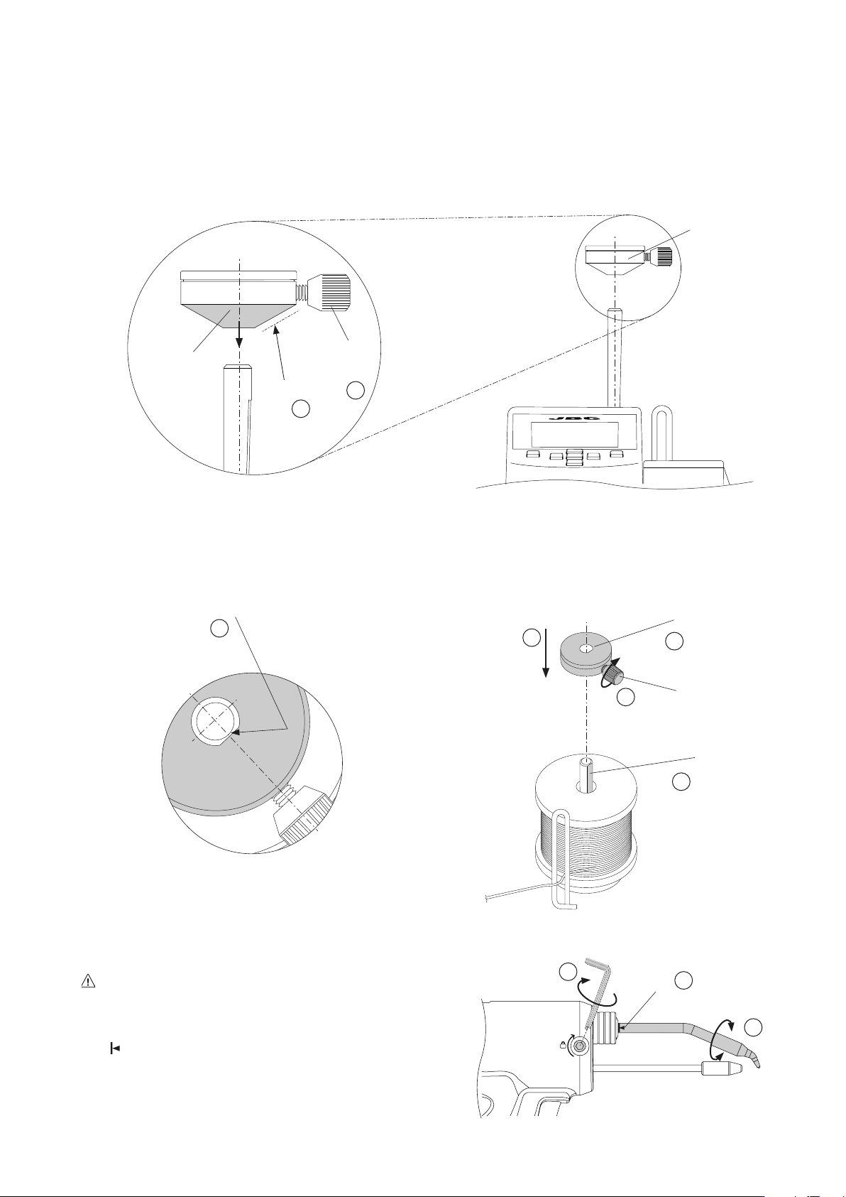
Mark
Step 3 Cartridge Assembly
For a safe cartridge assembly/change, make sure that the tool is
unplugged and the cartridge has cooled down.
Loosen the cartridge set screw (1) and insert the cartidge up to its
mark (2). Important: It is essential to insert the cartridge completely
for a good connection.
Adjust the tip direction (3) and tighten the cartridge set screw (1).
Top View
of the Reel Locking
Flat Side
(Reel Locking and Axis)
Reel Locking
Screw
Flat Side
of the Axis
Flat Side of the
Reel Locking
Step 2 Reel Locking Assembly
Reel Locking
Reel Locking
Conical
Side
To assemble the reel locking, its conical side must be pointing
downwards (1).
Make sure that the reel locking screw is slightly backed out and does
not collide with the axis (2).
Align the flat side of the axis with the inner flat side of the reel locking
(3) and assemble the reel locking to the axis (4).
Note: To prevent the solder reel from spinning freely or binding, gently
press the reel locking down, but only enough to allow the solder reel
to rotate freely, before tightening the reel locking screw (5).
Reel Locking
Screw
EARTH FUSE F1.25 A
USE ONLY WITH A 250 V FUSE
EARTH FUSE F1.25 A
ALE250
ALE250
ALE250
6
3
1
2
4
5
3
1
2
5
40 mm
50 mm
60 mm
80 mm
100 mm
130 mm
130 mm
para manuales - negro plano
200 mm
300 mm
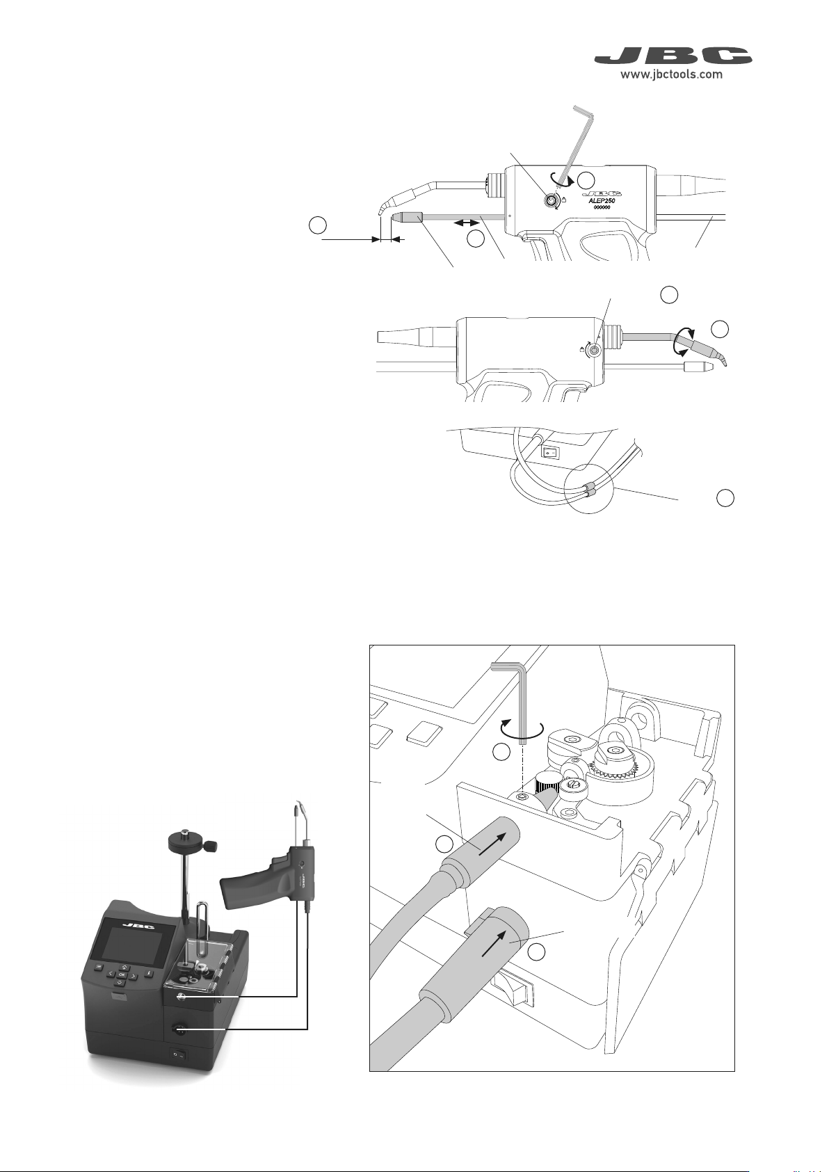
ALEP250
Angled Automatic-Feed Soldering Iron
Guide
Nozzle
Tool Connector
Connect the tool to the control unit following
these steps:
Loosen the set screw (1), insert and push
the guide nozzle until it stops (2) and tighten
the set screw (1).
Then plug in the tool connector (3).
Step 5 Tool Assembly
Loosen the guide tube set screw (oppo-
site direction to that indicated on the tool
casing) (1) and insert the guide set.
Adjust the guide tube length (2). Leave a gap
of 5 to 7mm (0.197 to 0.276in) between the
tip and the outlet nozzle (3).
If necessary adjust the cartridge tip direction
(4) to match the point where the wire will
come out. To do this, open the cartridge
set screw and tighten it when it is done (5).
Once the guide tube set position is adjusted
tighten the guide tube set screw (1).
For a better handling use the clips (6) to band
the guide tube and the tool cable together.
Step 4 Guide Set Assembly
Clips
Outlet
Nozzle
Guide Nozzle
5-7 mm
0.19-0.27 in
Guide Tube
Set Screw
Guide Set
Cartridge Set
Screw