Printer 710_810 v8 High Throughput Conveyor Module.pdf - 第22页
HIGH THROUG HPUT CONVEY OR (HTC) MOD ULE ADJUS TMEN TS AND SE TTINGS 17.22 Technical Reference Manual Chapter Issue 3 Oct 06 Rear Snugger Plate Parall elism 1. Open the f ront pri nthead cover /shutter . 2. Slacken t he …
HIGH THROUGHPUT CONVEYOR (HTC) MODULE
ADJUSTMENTS AND SETTINGS
Chapter Issue 3 Oct 06 Technical Reference Manual 17.21
Snugger Base
Plate Height
Adjustment
NOTE
The Board Clamp Setting is also valid for snuggers, this is factory set and
shouldn’t normally need to be adjusted. If adjustment is necessary carry out
Board Clamp Setting, substituting snugger base plate for rear board clamp and
fixed snugger plate for front board clamp.
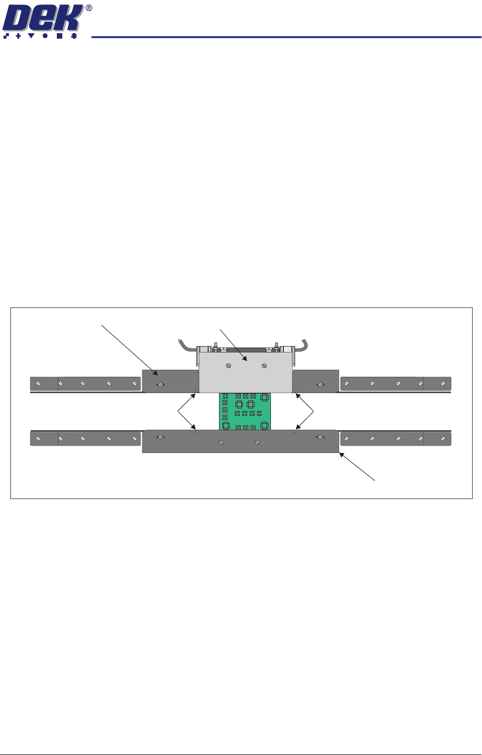
The snugger base plate and the front snugger plate are height adjustable to
accommodate for different board thicknesses.
1. Place a product board centrally between the snuggers.
2. In Diagnostics select Rail System.
3. Select Select Module.
4. Select Toggle Board Clamp.
5. Select Run Diagnost.
6. Open the front printhead cover.
7. Adjust the two downstop screws on the snugger base plate so that the top
of the board and the rear snugger plate are aligned.
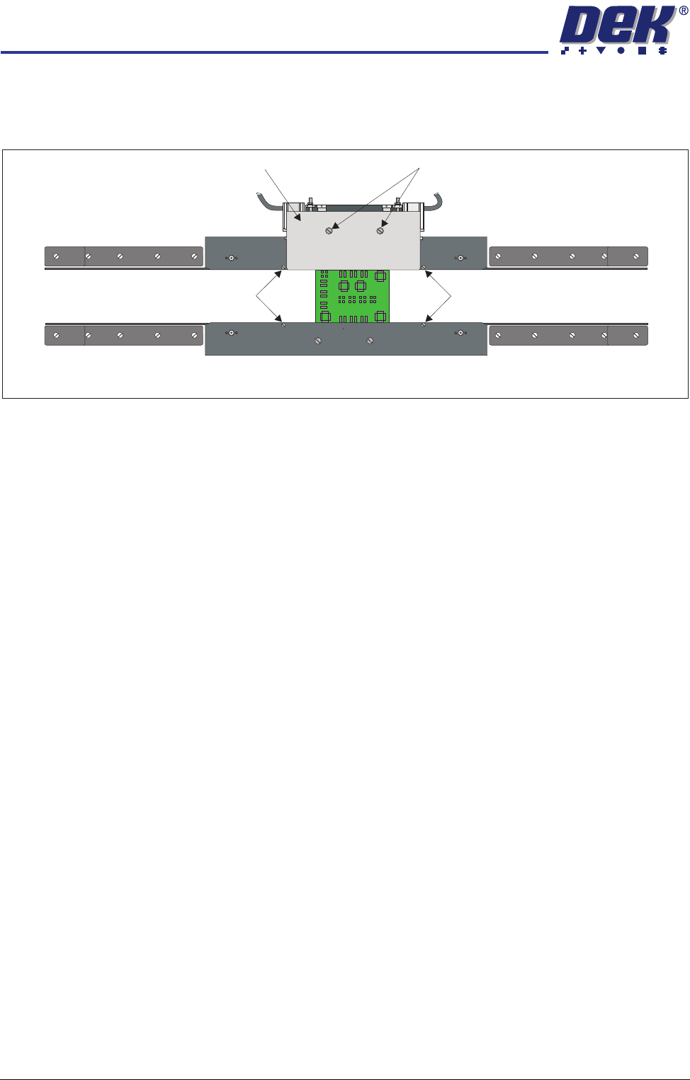
8. Adjust the two downstop screws on the front snugger plate so that the top
of the board and the front snugger plate are aligned.
9. Close the front printhead cover.
10. Press the System button.
11. Select Toggle Board Clamp.
12. Select Run Diagnost.
13. Remove the product board from the machine and exit from diagnostics.
Downstop Screws
Downstop Screws
Fixed Rail
Moving Rail
Rear Snugger Plate
Front Snugger Plate
Plan View of Rail System (Showing Board Clamped)
Snugger Base Plate
HIGH THROUGHPUT CONVEYOR (HTC) MODULE
ADJUSTMENTS AND SETTINGS
17.22 Technical Reference Manual Chapter Issue 3 Oct 06
Rear Snugger
Plate Parallelism
1. Open the front printhead cover/shutter.
2. Slacken the two rear snugger plate securing screws.
3. Place a product board centrally between the snuggers.
4. In Diagnostics select Rail System.
5. Select Select Module.
6. Select Toggle Board Clamp.
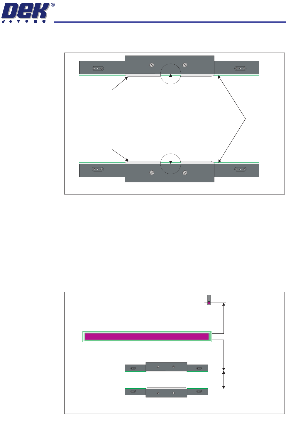
7. Select Run Diagnost. The edge of the rear snugger plate aligns with the
edge of the board.
8. Tighten the two rear snugger plate securing screws.
9. Remove the product board from the machine and exit from diagnostics.
Home Position Rail
Width Check
Ensure that board clamps are fitted and that the Board Clamp Setting procedure
(this section refers) has been carried out.
1. In Diagnostics select Rail System.
2. Select Select Module.
3. Select Home Rail Width.
4. Select Run Diagnost.
5. Select Adjust and set board width to 250mm.
6. Select Exit.
7. Select Drive Rail to Board Width.
8. Select Run Diagnost.
9. Open the front printhead cover/shutter.
Downstop Screws
Downstop Screws
Rear Snugger Plate Rear Snugger Plate Securing Screws
Plan View of Rail System
HIGH THROUGHPUT CONVEYOR (HTC) MODULE
ADJUSTMENTS AND SETTINGS
Chapter Issue 3 Oct 06 Technical Reference Manual 17.23
10. Place a vernier gauge above the transport belts in the centre of the board
clamps and check that the vernier reads between 250.25mm ±0.10mm.
11. If the rail width is correct, go to Step 21.
12. Close the printhead cover/shutter and press the System button.
13. Select Set Rail Board Width Calibration.
14. Select Run Diagnost to open the Rail Width Offset window.
15. Use Incr. or Decr. to set the offset required to achieve the dimension in Step
10.
NOTE
Increasing the offset increases the dimension between the rear rail and the
home position therefore, decreasing the width between the front and rear
rails.
16. Select Move.
17. Open the front printhead cover/shutter and recheck the measurement.
250.25mm ±0.10mm
Rear Board Clamp
Plan View of Board Clamps
Transport Belts
Front Board Clamp
Plan View of Transport Rails (centre section)
Home Position
Rail Width
RAIL WIDTH OFFSET 0.00 mm
+/- 3.00mm