00198356-01_AI_Input-Extension_SX12_DE_EN_web.pdf - 第58页
3 Installation 3.3 Preparing the extensions Assembly Instructions / Montageanleitung SIPLACE SX1/SX2 V2 Option Input Conveyor Extension 05/2017 58 3.3 Preparing the extensions This section describes how to prepare the in…
Assembly Instructions / Montageanleitung SIPLACE SX1/SX2 V2
Option Input Conveyor Extension 05/2017
3 Installation
3.2 Dismantling any available belt guides
57
3.2 Dismantling any available belt guides
This section describes how to dismantle the belt guides which are installed in the standard con-
veyor.
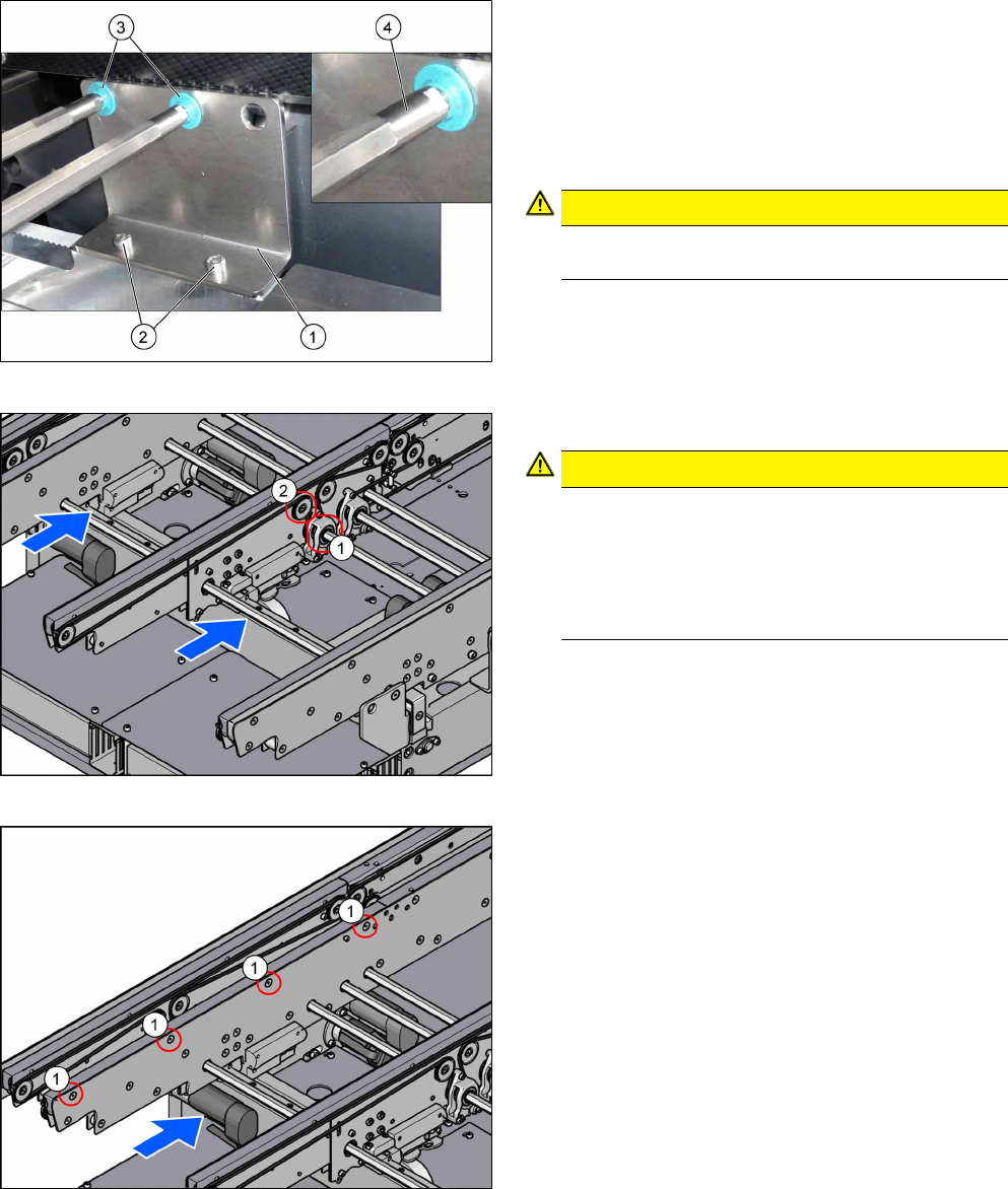
Fig.8: Hexagonal shaft
In order to unthread the conveyor belt, the hexagonal
shaft of the corresponding drive must be dismounted
(see the next steps).
To do so, proceed as follows:
► Remove the screws (2) that are fastening the
bracket (1). See also: 4.1.1 "Replacing the
Hexagonal Shaft [03094006-xx]" [}63].
CAUTION!
Make sure you do not lose the green plastic
bearings(3).
.
If required, use two fork wrenches to dismantle the
ends (4) of the hexagonal shafts. This makes more
room for moving the hexagonal shafts.
Fig.9: Movable idler pulley and drive
► Loosen the movable idler pulley (2).
CAUTION!
Only loosen!
Make sure you do not unscrew the movable idler
pulley completely. Otherwise, the counterpart in-
side the conveyor rail may fall out.
The lack of room makes subsequent insertion
and fixture of the counterpart highly complicated.
.
For an overview of the individual movable idler pulleys,
see section 4.1.6 "Belt Tension" [}69].
► Remove the screws fastening the drive (1) of the
hexagonal shaft. See also: .4.1.2 "Replacing the
Tape Drive [03092315-xx]" [}64]
Fig.10: Belt guide
► Dismount the belt guide. To do so, remove the
four countersunk screws (1) at the upper side of
the conveyor rails.
See also: 4.1.4 "Replacing the clamping rail and
belt guide" [}66].
► Unthread the conveyor belt.
See also: 4.1.5 "Replacing the Toothed Belt
(Conveyor Belt)" [}68]
► Repeat these steps for all conveyor rails.
3 Installation
3.3 Preparing the extensions
Assembly Instructions / Montageanleitung SIPLACE SX1/SX2 V2
Option Input Conveyor Extension 05/2017
58
3.3 Preparing the extensions
This section describes how to prepare the input conveyor extensions for the installation:
●
Input conveyor extension A/C complete [03127428-xx]
●
Input conveyor extension B/D complete [03127427-xx]
NOTICE
Example
The "Input conveyor extension A/C complete" [03127428-xx] is taken as an example to
show the preparation of the extensions.
The preparation of the "Input conveyor extension B/D complete" [03127427-xx] follows the
same procedure.
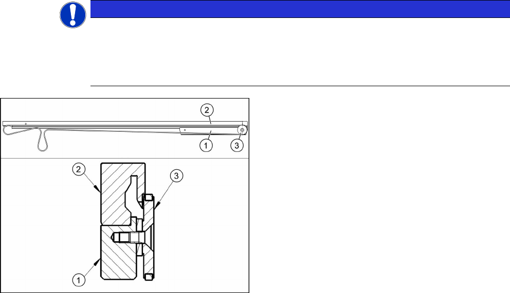
Mounting the stiffening bar (example shows the con-
veyor rail A/C)
1. Stiffening bar (idler pulley mount) [03127457‑xx]
2. Belt guide extension [03127426‑xx]
3. Idler pulley [03099834‑xx]
► Use three screws of type ISO4762-M3x12-A2-70
[03042544 xx] to fasten the stiffening bar(1) to
the belt guide extension(2).
► Dismount the idler pulley (3) from the dismantled
belt guide and mount it on the belt guide exten-
sion.
► Repeat these steps for all conveyor rails.
Assembly Instructions / Montageanleitung SIPLACE SX1/SX2 V2
Option Input Conveyor Extension 05/2017
3 Installation
3.4 Installing the belt guide extension
59
3.4 Installing the belt guide extension
This section describes how to install the belt guide extensions on the machine:
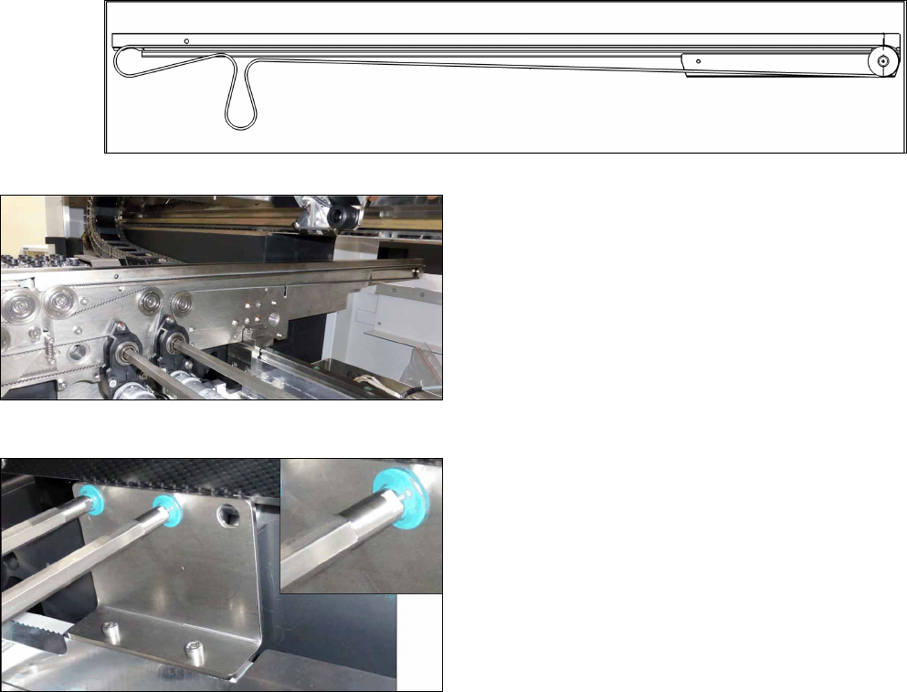
Fig.11: Belt tensioning with belt guide extension (example shows conveyor rail A/C)
Fig.12: Toothed belts and drive
► Thread in the toothed belt (L=1653mm)
[03127522‑xx].
See also: 4.1.5 "Replacing the Toothed Belt
(Conveyor Belt)" [}68].
► Mount the belt guide extension on the conveyor
(torque 6 Nm).
See also: 4.1.4 "Replacing the clamping rail and
belt guide" [}66].
► Mount the drive (torque 1.7 Nm).
See also: 4.1.2 "Replacing the Tape Drive
[03092315-xx]" [}64].
► Mount the hexagonal shaft.
See also: 4.1.1 "Replacing the Hexagonal Shaft
[03094006-xx]" [}63].
► Repeat these steps for all conveyor rails.