SJ3901DCB1-06E_mail.pdf - 第6页
10 11 Resolution Height measurement range Image capture time Major characteristics Meets requirements for production of advanced smart phones, wearable devices, and devices and modules for IoT. Capable of 0201mm (008004i…
6 7
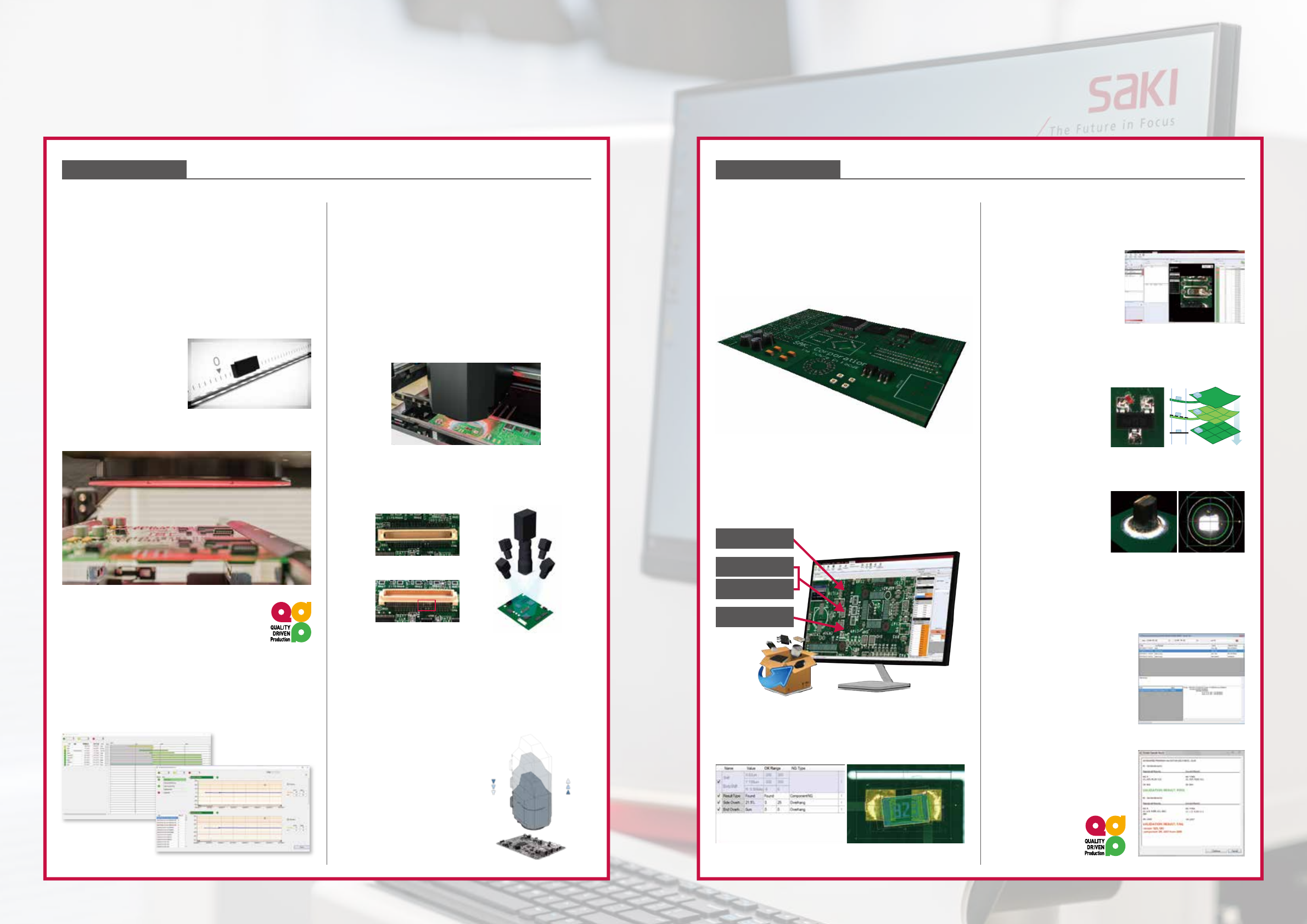
Key Factor 2
Advanced Software Features
Applied Technology
SAKI Technology for M2M Communication
Key Factor 1
Advanced Hardware Features
Proprietary Hardware provides
accurate measurements
⁃
Saki's machines are built with hardware that's made
to last.
⁃
A closed-loop, dual servo-motor drive system, high-
resolution linear scale, and rigid gantry structure
provide unsurpassed accuracy and repeatability for
absolute measurements.
⁃
An optimized conveyor
system, driven by step
motors, enables fast
PCBA loading and
unloading.
Self-diagnostic System
Saki's predictive and preventive maintenance
management system assures stable machine
conditions and repeatable, consistent performance.
Every key component is monitored along with system
conditions, and a detailed diagnostic log is recorded.
The optimized preventive maintenance plan reduces
maintenance time, machine down-time, manpower,
and costs.
Optical Unit
⁃
Four, multi-frequency digital projectors provide
accurate 3D measurements for high-quality images.
⁃
Three camera resolution levels—7µm, 12µm, 18µm—
are available to match application requirements.
⁃
Saki's CoaXPress interface in the overhead camera
captures images 1.7 times faster than previous models.
⁃
Enhanced 2D and 3D calibration uses multiple
calibration height targets for positive and negative
heights to guarantee height measurement accuracy.
Side Cameras *factory-installed option
A quad side camera system ensures inspection of the
entire board, including dead angles and areas missed
by overhead cameras.
Advantages of the new Z-axis package for the
3Di Series:
*factory-installed option
⁃
Extends maximum height-measurement range up to
40mm;
⁃
Uses standard AOI equipment to inspect special
components such as tall press-fit pins;
⁃
Enables accurate defect
detection and optical
character recognition (OCR)
of tall components;
⁃
Provides accurate inspection
when the PCB assembly is
clamped in a jig, allowing
standard AOI to tackle PCB
back-end processes.
Programming
⁃
Special BF2 software has a common user-interface
for Saki's 3D SPI, AOI, and AXI systems.
⁃
The software saves a full 3D image of the whole
PCBA, so the operator can create inspection data
without using the physical board.
⁃
Saki Self-Programming (SSP) Software
Saki's Self-Programming Function was developed on
the concepts of Board less, Skill less, and Stress less.
Inspection data can be easily created by using various
PCB design data in addition to Gerber data and CAD
data.
Inspection Data per IPC Standards
Default thresholds of inspection data conform to IPC
standards.
Measurement Inspection and
Tuning Function
Offline Debugging
Operator can edit
inspection data to check
previous Good/NG images,
or real-time defect images,
offline without any
production interruptions.
Warpage Adjustment
Warpage is compensated automatically. An accurate
height map is made
of the entire PCBA
surface, enabling the
Extra Component
Detection function to
detect foreign material.
Fujiyama (Through-hole Device Solder Inspection)
The Fujiyama algorithm
provides complete
through-hole joint
inspection in a single
step. It simultaneously
inspects for copper
exposure, pin detection,
pin-holes, solder fillets, and bridges.
Inspection Data Verification
History Management
System
The History Management
System records the detailed
data modification system
in detail (who, what, when,
where, why, and how)
Golden & Silver Sample
Check Function
Maintains inspection accuracy
by checking machine status
and inspection conditions
before starting auto
operation.
Time Based Maintenance
Condition Based Maintenance
TOP Camera Image
SIDE Camera Image
Gerber
Gerber
CAD XY
ECAD Design
Height ECD function
3D DIP Soldering
Linear scale image
3D-SPI 3D-AOI 3D-AOI 3D-AXI UnloaderPrinter
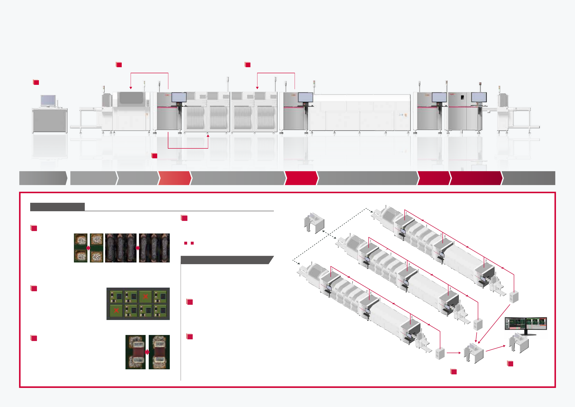
Feed-back from SPI to Printer
1
Feed-back from AOI to Pick-and-Place machine
※1
3
Automated line
control function
4
Feed-forward from SPI to Pick-and-Place machine
ReflowLoader
Management terminal
Pick-and-Place
2
8 9
Solution
Saki's QUALITY DRIVEN Production Solution
Key Factor 3
Applied Technology
M2M Solution
1
Feed-back from SPI to Screen Printer.
Feeds back
misalignment
data and prevents
print errors by
automatically
alerting the user
when the stencil
needs cleaning.
2
Feed-forward from SPI to
Pick-and-Place machine
Measures the degree the printing
position shifts to correct placement
positioning. A NG board skip function
improves efficiency, quality, and
cost.
3
Feed-back from AOI to Pick-and-Place
machine
Feeds back placement position and location
data from AOI to pick-and-place and feeds
forward data from SPI to improve quality and
efficiency.
*1 factory installed option
4
Automated line control function
Automates control of the assembly line
to reduce rework and waste and increase
throughput.
※
1
〜
4
Saki partners with the leading PCB equipment
manufacturers. Ask us which products we connect
with.
BF2-Editor
Create data and debug the process offline
BF2-Monitor
(Offline verification terminal)
5
RMS (Remote Management System)
Remotely control multiple BF2-Monitors
with a single PC. Reduces assembly-floor
personnel. Moreover, the production status
of each device can be confirmed.
6
MPV (Multi Process View)
The BF2-Monitor shows the results of all
inspection processes (SPI, pre-reflow, and
post reflow) on one screen in real time for
operator review, simplifying the verification
process and making it less subject to error.
It is also useful for analyzing the cause of a
defective board.
Correction of
the print position
Automatic
cleaning instructions
NG board skip
Placement position
correction*
1
Options
6
5
Dual Monitor
3D-AOI
(Post Reflow)
3D-AOI
(Post Reflow)
3D-AOI
(Post Reflow)
BF2-Monitor
BF2-Monitor
BF2-Editor
Server
Server
MPV
RMS
Line 1
Line 2
Line 3
(MPV DATA)
(MPV DATA)
10 11
Resolution
Height
measurement
range
Image
capture time
Major
characteristics
Meets requirements for
production of advanced smart
phones, wearable devices, and
devices and modules for IoT.
Capable of 0201mm (008004in.)
component inspection.
Well balanced system
offering both high speed
and the inspection of
the industry's smallest
components.
Saki's new optical sensor
increases speed by 170%
delivering the industry's
highest throughput.
7μm 12μm 18μm
4mm,
0.15in.
10mm,
0.39in.
1,063mm
2
/s
1.64in.
2
/s
3,600mm
2
/s
5.58in.
2
/s
5,700mm
2
/s
8.83in.
2
/s
High definition High speed
20mm,
0.78in.
Product
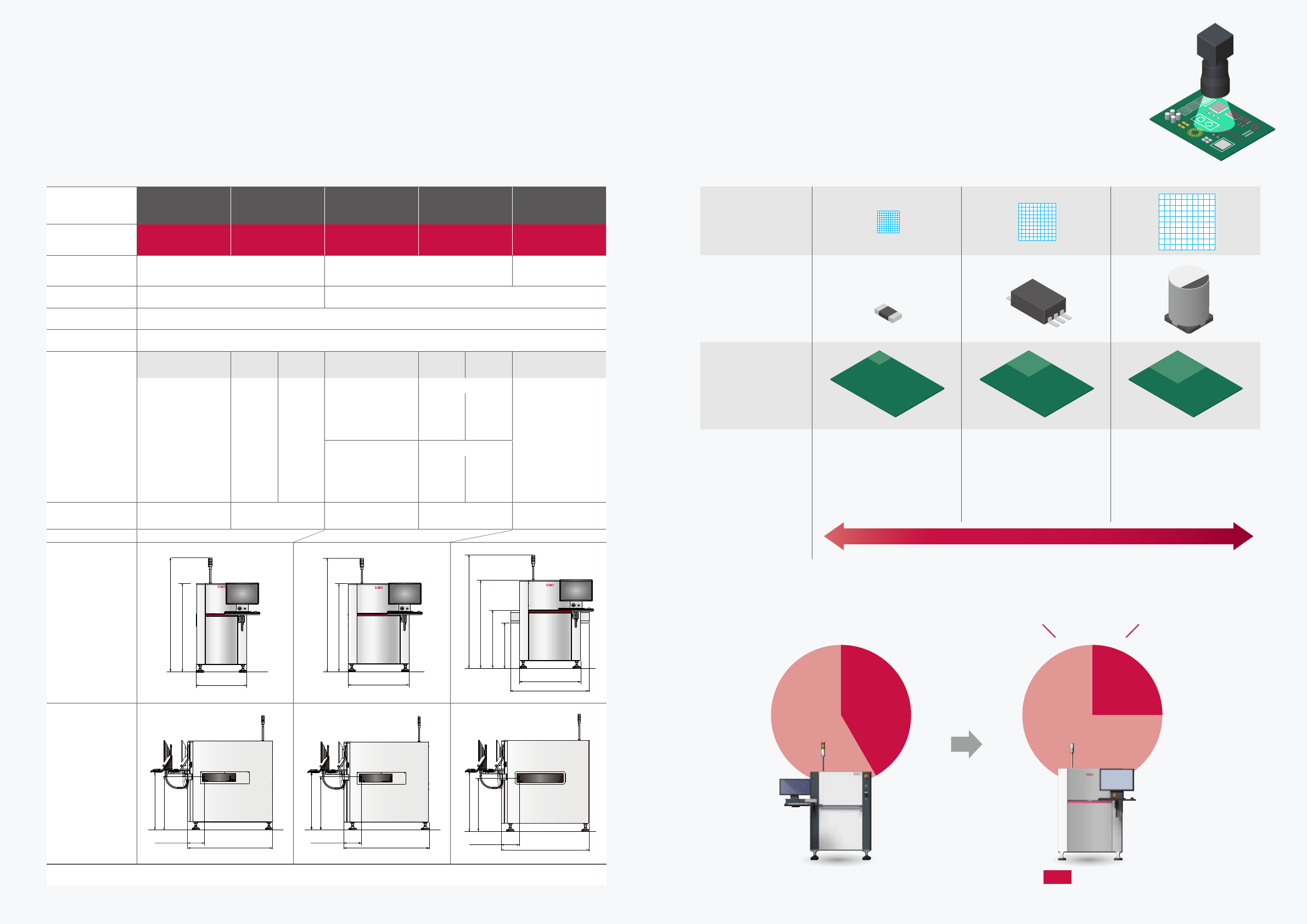
3Di Series Product Specifications
3Di Series Optical Unit Specifications
Dual-lane system can inspect 2 different PCBAs simultaneously
Wide selection of cameras based
on various optical resolutions and speeds
Substantially improves inspection speed
Comparison between BF-3Di and 3Di-LS2 using an optical unit with
18μm resolution and PCB size 330x250mm(12.99x9.84in.).
Front View
(mm, in.)
850 ,33.46
(1500 ,59.05)
(1930 ,75.98)
1040 ,40.94
(1500 ,59.05)
(1930 ,75.98)
1040 ,40.49
1340 ,52.75
(1500 ,59.05)
(1930 ,75.98)
(775 ,30.51)
(986 ,38.81)
Side View
(mm, in.)
285, 11.23
1430, 56.30
(1000, 39.37)
(900, 35.44)
295, 11.62
1440, 56.70
(1000, 39.37)
(900, 35.44)
295, 11.62
1440, 56.70
(1000, 39.37)
(900, 35.44)
15SEC
BF-3Di
3Di-LS2
25SEC
NEW
Faster !
Dimensions
M
Single lane
M
Dual lane
L
Single lane
L
Dual lane
XL
Single lane
Model Name
3Di-MS2 3Di-MD2 3Di-LS2 3Di-LD2 3Di-ZS2
Size (W)×(D)×(H)
(mm, in.)
850 × 1430 × 1500,
33.46 × 56.30 × 59.06
1040 × 1440 × 1500,
40.94 × 56.69 × 59.06
1340×1440×1500,
52.75×56.69×59.06
Weight
850kg, 1873.93lb 900kg, 1984.16lb
Electric Power
Single Phase 〜 200-240V+/-10%, 50/60Hz
Air Requirement
0.5MPa, 5L/min(ANR)
PCB Size
(mm, in.)
ー
Single
mode
Dual
mode
ー
Single
mode
Dual
mode
ー
50×60〜330×330,
1.97×2.36〜
12.99×12.99
50×60〜
330×330,
1.97×2.36〜
12.99×12.99
50×60〜
320×330,
1.97×2.36〜
12.60×12.99
【7μm camera head】 【7μm camera head】
50×60〜686×870,
1.97×2.36〜27.00×34.25
50×60〜330×330,
1.97×2.36〜12.99×12.99
50×60〜
330×330,
1.97×2.36〜
12.99×12.99
50×60〜
320×330,
1.97×2.36〜
12.60×12.99
【
12/18μm camera head
】 【
12/18μm camera head
】
50×60〜500×510,
1.97×2.36〜19.68×20.07
50×60〜
500×510,
1.97×2.36〜
19.68×20.07
50×60〜
320×510,
1.97×2.36〜
12.60×20.07
PCB Clearance
Top:40mm, 1.57in.
Bottom:60mm, 2.36in.
Top:40mm, 1.57in.
Bottom:50mm,1.96in.
Top:40mm, 1.57in.
Bottom:60mm, 2.36in.
Top:40mm, 1.57in.
Bottom:50mm, 1.96in.
Top:40mm, 1.57in.
Bottom:60mm, 2.36in.
⁃
3Di-ZS2 supports the optical unit
with resolution of 18µm.