00193351-06_RI_Vacuum_pump_de en.pdf - 第51页
SIPLACE HS-50/HS-60/D4/S-25HM/S-27HM/HF -Series 2 Retrofit instructions for vacuum pump 07/2011 Edition 49 2 : Remove the blind plugs. : Connect the two 12 mm hoses to the new co mpressed air distr ibutor (only C&P p…
2 Retrofit instructions for vacuum pump SIPLACE HS-50/HS-60/D4/S-25HM/S-27HM/HF-Series
07/2011 Edition
48
2.5 SIPLACE HF
2.5.1 Necessary parts
Connection kit vacuum pump HF: (Item no. 00119696-01) 2
Vacuum pump (item no. 00119794-xx) 2
2.5.2 Necessary tools
Set of Allen keys 2
Set of flat wrenches 2
Philips screwdriver 2
2.5.3 Modification of compressed air supply holding and placement circuit
: Switch the placement machine off at the main switch.
: Open the door of the compressed air supply.
: Close the main compressed air stopcock.
: Close the stopcock.
: Remove both 12 mm compressed air hoses at both stopcocks.
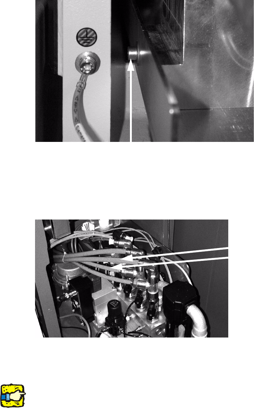
: Screw the new compressed air distributors onto the left side of the housing.
SIPLACE HS-50/HS-60/D4/S-25HM/S-27HM/HF-Series 2 Retrofit instructions for vacuum pump
07/2011 Edition
49
2
: Remove the blind plugs.
: Connect the two 12 mm hoses to the new compressed air distributor (only C&P placement
heads).
: Plug both blind plugs into the open connections of the compressed air distributor.
2
2.5.4 Change of vacuum generator
: Change the vacuum generator DLM2 against the vacuum generator for vacuum pump.
2
Mind the right allocation of hoses! 2
Fixing screw (thread is there, eventually drill a hole
Change hose (12 mm)
against blind plugs

2 Retrofit instructions for vacuum pump SIPLACE HS-50/HS-60/D4/S-25HM/S-27HM/HF-Series
07/2011 Edition
50
2
2
: Open the compressed air stopcock.
: Pull the compressed air supply back into the placement machine.
: Close the door of the compressed air supply.
: Switch the placement machine on at the main switch.
2
2
For checking the vacuum values see page 23 ff. 2
2
2
2
2
2
2
2
2
2
2
2
2
2
2