00193922-03.pdf - 第214页
4 Setting up and commissioning User manual SIPLACE HF series 4.4 Setting up the placement machine Software Version SR.50x .xx 01/2006 US Edition 214 4.4.12.3 Fitti ng the HF/3 axis unit (gantry 1 and gantr y 4) Æ Careful…

User manual SIPLACE HF series 4 Setting up and commissioning
Software Version SR.50x.xx 01/2006 US Edition 4.4 Setting up the placement machine
213
4.4.12.2 HF/3 axis unit (gantry 1 and gantry 4) - Connecting the plugs
Æ Connect the power cable as shown in the following diagram:
4
4
4
Æ Check the switch settings for S1
1: OFF
2: OFF
Axis unit
Gantry 1 and gantry 4
Plug
Connecting cable
NOTE
Plug Cable
X31 X31
03009762
03009763
03009764
03009765
03009766 W1-W5
Secure connector with clips
X32 X32
03009822
03009823
03009824
03009825
03009827
Secure connector with clips
X4sr X4sr 03009760 Snap connector into place
X4st X4st 03009761 Snap connector into place
X4vr X4vr 03009820 Snap connector into place
X4vt X4vt 03009821 Snap connector into place
X1so
X3so
X5so
X1so
X3so
X5so
03009771
03009772
03009773
Insert as far as the stop
X1sp
X3sp
X5sp
X1sp
X3sp
X5sp
03009774
03009775
03009776
Insert as far as the stop
X1vo
X3vo
X5vo
X1vo
X3vo
X5vo
03009831
03009832
03009833
Insert as far as the stop
X1vp
X3vp
X5vp
X1vp
X3vp
X5vp
03009834
03009835
03009836
Insert as far as the stop
X30_1tq
X30_2tq
X30_1tq
X30_2tq
03010051
03010051
Screw tightly

4 Setting up and commissioning User manual SIPLACE HF series
4.4 Setting up the placement machine Software Version SR.50x.xx 01/2006 US Edition
214
4.4.12.3 Fitting the HF/3 axis unit (gantry 1 and gantry 4)
Æ Carefully lift the axis unit onto the rail in the extension kit.
Æ Make sure that you do not squash any cables.
Æ Push the axis unit into the extension kit as far as the stop.
Æ Connect the fan cable to the axis unit cable.
Æ Secure the axis unit with the fillister head screw.
Æ Insert the cover.
Æ Fix the grounding cable to the doors (item 2 in Fig. 4.4 - 15, page 201), as shown in Fig.
4.4 - 17
on page 205.
Æ Lock the doors.
4.4.12.4 Fitting the side plates
Æ Fix the grounding cable to each side plate (item 6 in Fig. 4.4 - 15, page 201), as shown in Fig.
4.4 - 17
page 205.
Æ Fix the side plate to the machine frame with 6 fillister head screws.
4
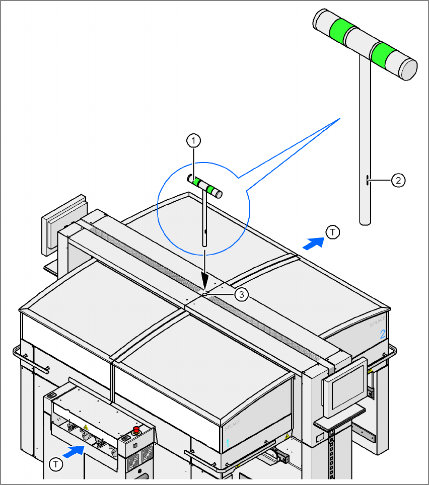
4.4.13 Fitting the main fault indicator
Æ Open the protective cover on location 2.
Æ Move the gantry out of the vicinity of location 2.
Æ Use the size 2.5 Allen key to loosen the four hexagon socket head screws of the long trailing
cable plate and lift out the plate.
Æ Insert the main fault indicator lamp (item 1, Fig. 4.4 - 22) into the hole (item 3, Fig. 4.4 - 22)
until the tube of the lamp projects sufficiently into the terminal beneath.
Æ Align the main fault indicator (item 1, fig. 4.4 - 22) so that the mark (item 2, fig. 4.4 - 22) points
to the right looking in the PCB direction of travel.
Æ Fix the main fault indicator in this position by tightening the two hexagon socket head screws
at the clamping point using the size 5 Allen key.
Æ Connect connector X55 on the main fault indicator (03004315-xx) to connector X55 on the
cable 03002529-xx.
Æ Fix the trailing cable plate using the four hexagon socket head screws.
User manual SIPLACE HF series 4 Setting up and commissioning
Software Version SR.50x.xx 01/2006 US Edition 4.4 Setting up the placement machine
215
4
Fig. 4.4 - 22 Fitting the main fault indicator
(1) Main fault indicator
(2) Mark
(3) Hole for the main fault indicator
(T) PCB direction of travel