00193922-03.pdf - 第215页
User manual SIPLAC E HF series 4 Setting up and commissioning Software Vers ion SR.50x.xx 01/2006 US Edition 4.4 Setting up the placement machine 215 4 Fig. 4.4 - 22 Fitting the main fault indicator (1) M ain fault i ndi…

4 Setting up and commissioning User manual SIPLACE HF series
4.4 Setting up the placement machine Software Version SR.50x.xx 01/2006 US Edition
214
4.4.12.3 Fitting the HF/3 axis unit (gantry 1 and gantry 4)
Æ Carefully lift the axis unit onto the rail in the extension kit.
Æ Make sure that you do not squash any cables.
Æ Push the axis unit into the extension kit as far as the stop.
Æ Connect the fan cable to the axis unit cable.
Æ Secure the axis unit with the fillister head screw.
Æ Insert the cover.
Æ Fix the grounding cable to the doors (item 2 in Fig. 4.4 - 15, page 201), as shown in Fig.
4.4 - 17
on page 205.
Æ Lock the doors.
4.4.12.4 Fitting the side plates
Æ Fix the grounding cable to each side plate (item 6 in Fig. 4.4 - 15, page 201), as shown in Fig.
4.4 - 17
page 205.
Æ Fix the side plate to the machine frame with 6 fillister head screws.
4
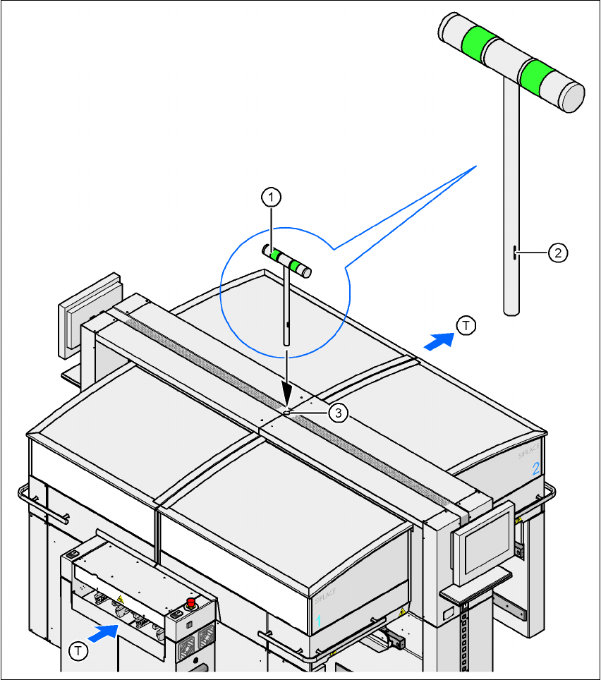
4.4.13 Fitting the main fault indicator
Æ Open the protective cover on location 2.
Æ Move the gantry out of the vicinity of location 2.
Æ Use the size 2.5 Allen key to loosen the four hexagon socket head screws of the long trailing
cable plate and lift out the plate.
Æ Insert the main fault indicator lamp (item 1, Fig. 4.4 - 22) into the hole (item 3, Fig. 4.4 - 22)
until the tube of the lamp projects sufficiently into the terminal beneath.
Æ Align the main fault indicator (item 1, fig. 4.4 - 22) so that the mark (item 2, fig. 4.4 - 22) points
to the right looking in the PCB direction of travel.
Æ Fix the main fault indicator in this position by tightening the two hexagon socket head screws
at the clamping point using the size 5 Allen key.
Æ Connect connector X55 on the main fault indicator (03004315-xx) to connector X55 on the
cable 03002529-xx.
Æ Fix the trailing cable plate using the four hexagon socket head screws.
User manual SIPLACE HF series 4 Setting up and commissioning
Software Version SR.50x.xx 01/2006 US Edition 4.4 Setting up the placement machine
215
4
Fig. 4.4 - 22 Fitting the main fault indicator
(1) Main fault indicator
(2) Mark
(3) Hole for the main fault indicator
(T) PCB direction of travel
4 Setting up and commissioning User manual SIPLACE HF series
4.4 Setting up the placement machine Software Version SR.50x.xx 01/2006 US Edition
216
4.4.14 Integrating the placement machine into the line
Æ Note the warning instructions described in section 4.4.2, page 176.
Æ The tools and equipment are listed in section 4.4.3, page 177.
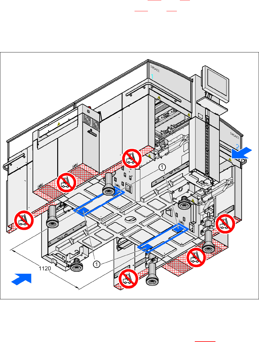
4.4.14.1 Positioning the fork-lift
4
Fig. 4.4 - 23 Contact surfaces - Forks across the direction of PCB transport
(1) Contact surfaces for the forks of the fork-lift
Æ Position the fork-lift across the direction of PCB transport and open the forks far enough so
that the machine's contact surface lies evenly on the forks (see Fig. 4.4 - 23
).