Infinity High Throughput Conveyor Module.pdf - 第3页
INFINITY +,*+7+ 528*+387&2 19(<2502' 8/( (/(&75,& $/6&+( 0$7,& Chapter Issue 1 May 03 Technical Reference Manual 15.3 ELECTRICAL SCHEMA TIC Breakout C CSK7 CSK2 Breakout D DPL1 DSK5 Front …
INFINITY
+,*+7+528*+387&219(<2502'8/(
02'8/(29(59,(:
15.2 Technical Reference Manual Chapter Issue 1 May 03
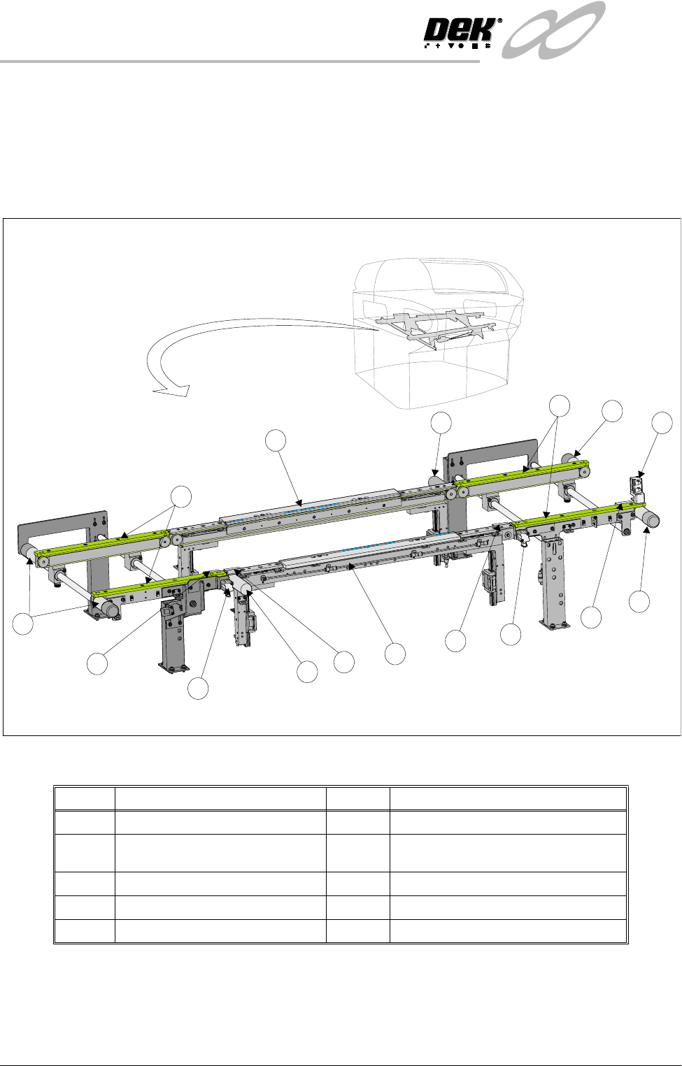
downline conveyor and one held on the print station. The maximum board
length is 370mm in three stage mode.
NOTE
Refer to the Sequences section of this chapter for more details of the single and
three stage operation in normal and fast modes.
Figure 15-1 High Throughput Conveyor Overview
Item Description Item Description
1 Print Station Transport Belt Motor 2 Auxiliary Conveyor
3 Auxiliary Conveyor Transport Belt
Motor
4 Conveyor Board Stop
5 Auxiliary Conveyor Sensor 6 Board at Right Sensor
7 Print Station - Fixed Rail 8 Board at Left Sensor
9 Print Station - Moving Rail
1
2
2
3
3
4
4
5
6
7
8
1
4
5
3
9
INFINITY
+,*+7+528*+387&219(<2502'8/(
(/(&75,&$/6&+(0$7,&
Chapter Issue 1 May 03 Technical Reference Manual 15.3
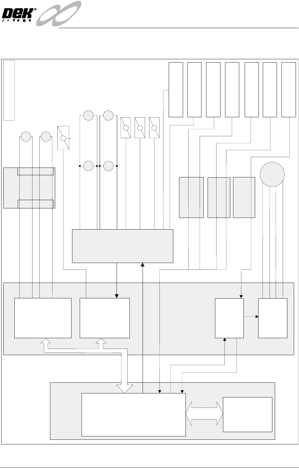
ELECTRICAL SCHEMATIC
Breakout C
CSK7
CSK2
Breakout D
DPL1
DSK5
Front Print Station
Belt Drive (8M03)
Rear Print Sation
Belt Drive (8M04)
Home
Board Clamp/Snugger
Solenoid (16SOL10)
Source 3
Right Auxiliary Rail
Sensor (27SE02)
DIG IN 16
DIG IN 17
Breakout B
BPL1
BSK3
Breakout A
APL1 ASK4
DIG IN 3
DIG IN 4
Machine PC
NextMove
Processor
ISA
BUS
CAN BUS
MUX Axis Home
Machine Controller
Stepper Direction
Stepper
Multiplexer
MultiMove
(X12)
MultiMove
(X13)
Dual Stepper
(X4)
Motor 2B-
Motor 2A-
Motor 2B+
Motor 2A+
M
M
Totem 0 (Fwd)
Totem 1 (Rev)
Totem 2 (Fwd)
Totem 3 (Rev)
Note: All Motors 24V dc
M
M
8M2
Moving Rail
Stepper
Rear
(27M04)
Rear
(27M02)
M
Front
(27M03)
M
Front
(27M01)
Right Auxiliary Rail
Belt Drive
Left Auxiliary Rail
Belt Drive
Conveyor Board Stop
(27SOL01)
Conveyor Board Stop
(27SOL02)
Conveyor Board Stop
(27SOL03)
Manual Operation
M27
3 Stage
Conveyor
Controller
Moving Rail Home
Sensor (8SE6)
Rail Lift Sensor
Right (8SE4)
Rail Lift Sensor
Left (8SE5)
Board at Right
Sensor (8SE7)
Board at Left
Sensor (8SE8)
Left Auxiliary Rail
Sensor (27SE01)
INFINITY
+,*+7+528*+387&219(<2502'8/(
31(80$7,&6&+(0$7,&
15.4 Technical Reference Manual Chapter Issue 1 May 03
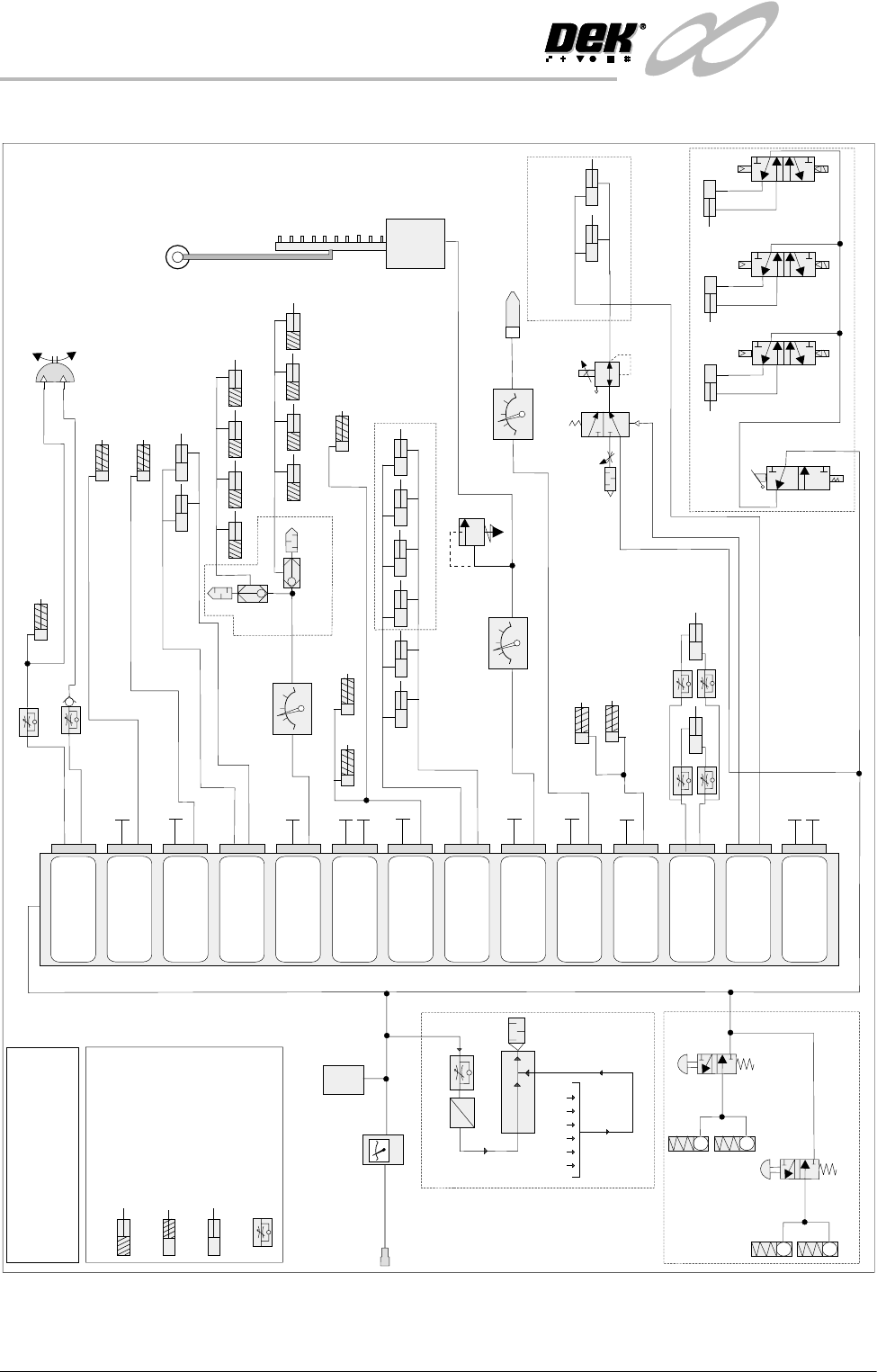
PNEUMATIC SCHEMATIC
Remote Board Stop
(optional)
A = Signal to Switch
B = Live
*
NOTE
Each solenoid has two parts A and B
Double Acting Cylinder
KEY
Single Acting Cylinder
(Piston retracted at rest)
Single Acting Cylinder
(Piston extended at rest)
Speed Control Valve
Vortex Cleaner Lift
(optional)
Screen Clamps
Pressure Relief Valve
(Infinity Only)
Pressure Regulator
Suction and
Filtration Unit
Underscreen
Cleaner
(optional)
Solvent
Tank
A
B
A
B
A
B
A
B
A
B
Board Stop
Screen Drive
Couple Left
(Infinity Only)
Screen Drive
Couple Right
(Infinity Only)
Screen Drive
Couple Rear
(Infinity Only)
Board Clamps
Spare
Cleaner Sqy Bar
Screen Clamps
Tank Pressure
Paste Dispense
Lid Bolt
Lid Bolt
ProFlow
(optional)
Autoflex
(optional)
High Throughput Conveyor Option
High Thro’put
Conveyor Option
Paste Dispenser
(optional)
Pressure Regulator
ProFlow - SCAR
Manifold
A
B
A
B
A
B
A
B
A
B
Lid Bolt
Autoflex
(Infinity Only)
ProFlow
SCAR
Spare
Screen Clean Squeegee Bar
(optional)
Board Clamps
A
B
Camera Board Stop
See Note
*
Screen Drive Couple Left
Screen Drive Couple Right
Screen Drive Couple Rear
Pressure Regulator
(optional)
A
B
A
B
A
B
Vacuum Tooling
Vacuum Tooling (optional)
Web Assembly
Locking Cartridge
Non Latching
Manual Valve
ASM Option (Horizon Only)
Filter
Regulator
Assembly
Mains Air
Connection
5 bar (min)
Pressure
Sensor