HS50电路图.pdf - 第18页
1 Detailed Circuit Diagr ams 18 0034307 0-020 101GD4 1 HS-50 co ntrol un it (vi ewed fr om the fro nt) 0034307 0-020 101GD4 2 HS-50 co ntrol un it (vi ewed from the ba ck) X2so X6so X7so X3sm Floppy Hard dis k o X2sn X6s…
1 Detailed Circuit Diagrams 17
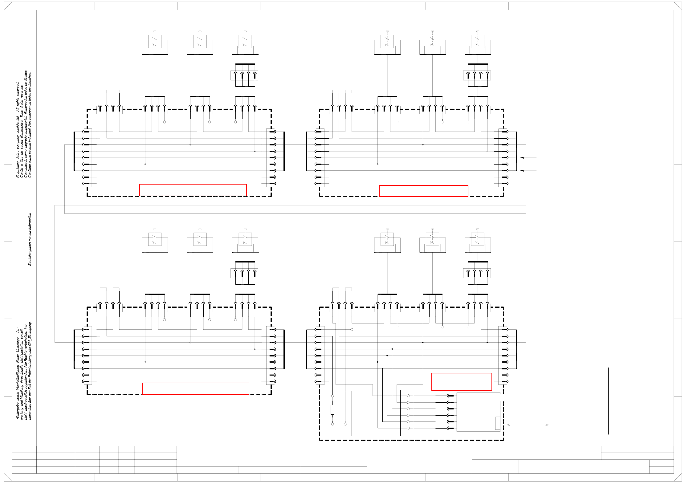
NOTHALT2 EMERG.-STOP loop, EMERG.-STOP buttons, protective switches (Sh. 2 of 2)
Function status
Product status
Doc. status
SMD Placement System SIPLACE HS50
NOTHALT-020101LD3
Replaced by
Sheet
Sh.
NOTHALT2.DWG
SD EA1 E2
CAD file:
Status Modified Date Name Stand.
Check.
Author
Date
Orig. Repl. f.
S826 b (S1) (S1) (S1)
1
3
2
4
7
8
9
8
9
7
5bl 5bl
yeye
N. u.
N. u.
N. u.
N. u.
See sheet 1
See sheet 1
bl 5 5bl
ye
N. u.
N. u.
7
8
9
7
8
N. u.
N. u.
ye
bl
55bl
8
9
7
N. u.
N. u.
ye
8
9
7
N. u.
N. u.
ye
5
bl
5bl
N. u.
N. u.
ye
9
8
7
8
9
7
N. u.
N. u.
ye
16a,c
17a,b,c
X8dm:1
X7dm:1
S_StartButton
S_StopButton
S_StopButton
S_StartButton
S826 b (S1) (S1) (S1)S826 b (S1) (S1) (S3)
S826 b (S1) (S1) (S3)
1
3
2
4
The wire colors in the drawing correspond to the Belden color code.
If cables are used corr. to the DIN 47100 color code, please use the table below!
Warning !
4
12
8
10
11
9
6
7
5
2
3
1
Wire
ye Yellowgn Green
libn Tan rd+bl
Yellow
Brown
Orange
Violet
ye
gy
pk
vi
Gray
Pink
bl
or
bn
Blue
rd
vi
gypk
bk
pk
bl
gy
Red+Blue
Red
Black
Violet
Gray+Pink
Gray
Pink
Blue
DIN 47100 color codeBelden color code
Black
Whitewh
rd
bk
Red
bn
gn
wh White
Brown
Green
Protective switches
Emergency-stop buttons
rd
or
bn
gn
bk+wh bk+wh
gn
bn
or
rd
bk+wh
gn
bn
or
rd
X300:7b
+24V
X300:7c X300:7a
+24V
X100:7a
+24V
X100:7b
+24V
X100:7c
+24V
X200:7c
+24V
X200:7b
+24V
X200:7a
+24V
+24V
X400:11c X400:9b
+24V
X400:9a
+24V
X400:9c
+24V
S_Comp. flap,
S_Comp. table,
S_Emerg. stop b.,
S_Cover,
X400
R1
X400
+24V
30a 30c
6-pole12-pole
12-pole 6-pole 12-pole
12-pole 6-pole
6-pole
6-pole
6-pole6-pole
6-pole
3
2
4
bk
wh
rd
gn
Cover, input
00335307-W1
13
21
14
22
ye
wh
bn
gn
13
21
00337737
0033773700337737
Emerg.-stop
(loop end)
wh
bn
gn
13
21
14
22
00335263
ye
wh
bn
gn
13
21
14
22
00335263
ye
wh
bn
gn
13
21
14
22
3
1
D
C
1
gn
3
1
4
2
bn
wh
ye
gn
3
1
4
2
bn
wh
ye
gn
3
1
4
2
bn
wh
ye
gn
Comp-ProtectiveFlap4
00337737
gn
wh
X82
00335262
00329698
CAN I/O module
bk+wh
rd
gn
bn
or
00335268
Status illustrated in this drawing:
covers closed,
emergency-stop buttons not pressed.
S_Cover
X17dm
A2 (dm)
X4dm:1
X9dm:1
X5dm:1
X3dm:1
125kbps
CAN bus
wh
rd
gn
X84
S_Emerg.StopB
S_Comp.Table
S_Comp. flap
rd
gn
rd
bk
Cover, output
D
3
C
B
A
5
B
32
F
41
E
5
4
F
Distributor, sector 4 (df)
rd
bkbn
rd
gn
bk+wh
4
1
3
bk+wh
8
A
2
gn
bk+wh
gn
rd
bn
Prot. cover 4
wh
rd
bk
X85
00335275
bn
rd
gn
bk+wh
gn
Prot. cover 1
wh
wh
X6df
X4dfX5dfX25df
00335266
X83
ye
00335306-W2
wh
Prot. cover 2
ye
gn
bk
bk
wh
bn
Emerg.-stop, output, righth. s.
bn
00335271
wh
gn
rd
bk
bk+wh
gn
rd
bn
gn
00335263
2
00335260
13
21
00335307-W1
Distributor, sector 2 (bf)
X3cf
X1cf X25cf X5cf X4cf
X6cf
Distributor, sector 3 (cf)
Comp-ProtectiveFlap3 Prot. cover 3
00337052
E
678
76
gn
bn
or
00335264
X3bf
gn
X1df
X3df
00335259
or
bn
gn
rd
bk+wh
or
bn
bk+wh
rd
X25afX1af
Distributor, sector 1 (af)
X6af
X4afX5af
X3af
22
14
1.
1.
2.
Hi
Hi
Hi
2
X6bf
X4bfX5bfX25bfX1bf
rd
gn
bn
or
bk+wh
rd 2
2
Emergency-stop loop
Hi
01.07.2001
01.07.01
01.07.01
01.07.01
bn
3K3
4
4
1
2
4
1
bk+wh
rd
15a,c
14a,c
gn
bn
6
20b
4
1
13a,c
24a,b,c
6
2
3
4
3
6
2
1
4
3
3
2
1
2
4
1
rd
bk+wh
1
3
gn
A5
2
4
A6
A3
1
3
A4
3
6
4
1
4
3
2
+24V
3
4
3
6
2
1
4
1
3
bn
bk+wh
rd
1
gn
2
6
4
A5
3
6
4
2
2
3
1
2
1
1
3
2
4
A6
A3
A5
gn
3
A4
1
4
2
6
3
1
3
2
2
4
4
1
3
A5
2
A4
A6
A3
4
1
3
bk+wh
rd
2
bn
2
4
A4
3
1
A3
A6
=
SIEMENS AG
+
2
4
3
1
4
00336152
0033618100336182
00336153
Comp-ProtectiveFlap2
00337052
ye
gn
bn
wh
14
22
00335263
ye
00337052
ye
gn
bn
wh
Comp-ProtectiveFlap1
00337052
ye
gn
bn
wh
gn
bn
wh
ye
gn
bn
wh
ye
gn
bn
wh
ye
1
3
4
2
bn
wh
ye
2
wh
rd
gn
bk
Emergency-stop, input, righth. s.
00335306-W2
1
See page 107
See page 105
See page 92
See page 97
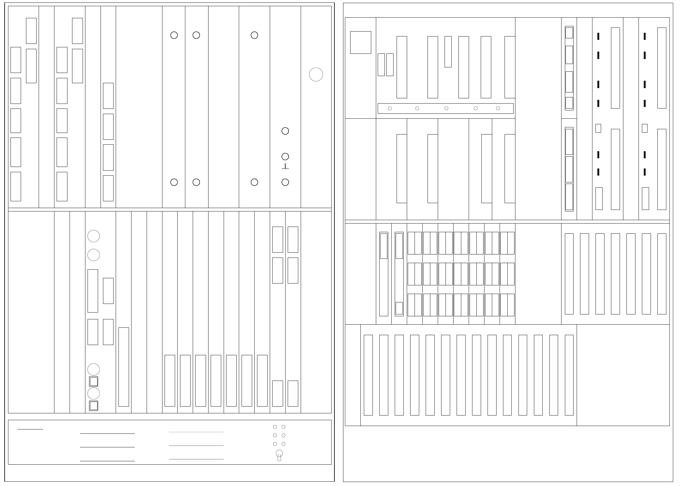
1 Detailed Circuit Diagrams 18
00343070-020101GD41 HS-50 control unit (viewed from the front)
00343070-020101GD42 HS-50 control unit (viewed from the back)
X2so X6so X7so
X3sm
Floppy
Hard disk o
X2sn X6sn X7sn
X3sk
X3sh
X3sg
X3sf
X3se
X3sd
X7sa
X6sa
X8sa
X9sa
X10
X5
X11 X12
LAN1 LAN2
M54
Axis board 1
Axis board 2
Axis board 3
Axis board 4
Axis board 5
Axis board 6
Axis board 7
COM 1 COM 2
Reserved for M54 GEM
Reserved for Floppy/Hard disk, GEM
Reserved for PCI
Spare
DIAGNOSIS
Reserved for PCI
Spare
+ 52V
+ 5V + 24V - 15V
+ 5V + 15V
- 12V
+ 12V
Battery +3.8V
X2sv X3sv X4svX1sv
Video multiplexer
ICOS 2
ICOS 1
X3su
X7su X9su X5su X8suX6su
X4su
X3st
X7st X9st X5st X8stX6st
X4st
Firmware Version : Axes :
Spare
X1
0
Y1
1
S1
2
X2
3
Y2
4
S2
5
X3
6
Y3
7
S3
8
X4
9
Y4
10
S4
11
Z1
12
D1
13
Z3
14
Z2
15
D2
16
D3
17
Z4
18
D4
19
20
BE
ON
IN
CE
0
ED
Board error
Initialized
Servo on
Count. error
Zero pulse
End
OFF Servo on
Servo off
Control unit, HS50 (viewed from the front)
00343070-020101GD41 05.11.99
X1sy
X2sy
X3sy
X4sy
X5sy
X6sy
X7sy
X8sy
X9sy
X10sy
X11sy
X12sy
X13sy
X14sy
X3sz
X4sz
X5sz
X6sz
X7sz
X1sz
X2sz
X4tr X2trX6tr
X3tr X1trX5tr
X4tq X2tqX6tq
X3tq X1tqX5tq
X4tp X2tpX6tp
X3tp X1tpX5tp
X4to X2toX6to
X3to X1toX5to
X4tn X2tnX6tn
X3tn X1tnX5tn
X4tm X2tmX6tm
X3tm X1tmX5tm
X4tk X2tkX6tk
X3tk X1tkX5tk
X25
X24
X22
X23
X20
X1th
X2th
X4th
X5th
X3th
X7th
X8th
X6th
X9th
1 2 3 4 5
X9tg
X10tg
X5tg X6tg X11tg
X8tg
X1tg X2tg X3tg X4tg
X9tf
X10tf
X5tf X6tf X11tf
X8tf
X1tf X2tf X3tf X4tf
1
X34 X33
1
1
X36
8
18
28
X35
1
2
3
26
Control unit, HS50 (viewed from the back )
00343070-020101GD42 05.11.99
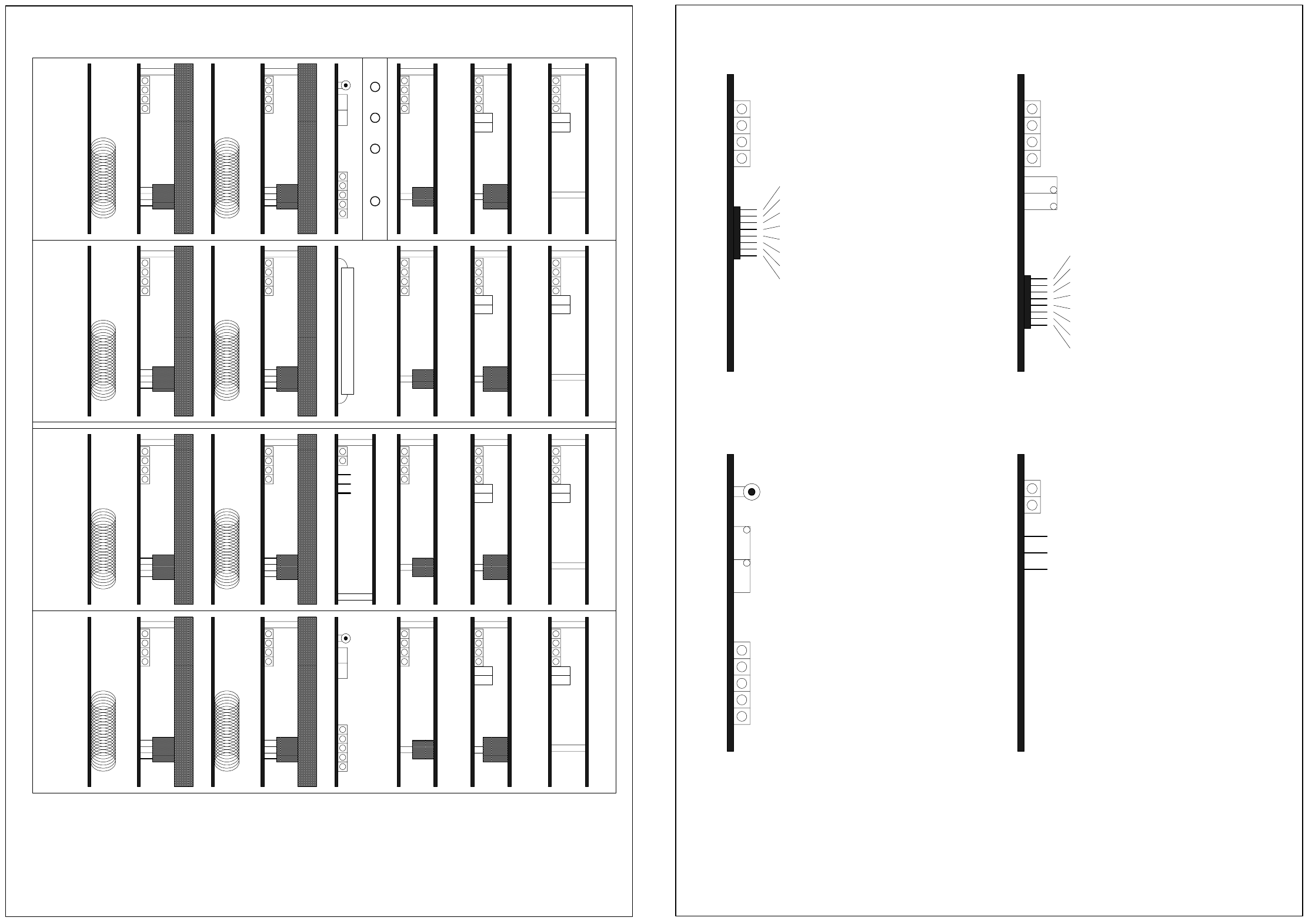
1 Detailed Circuit Diagrams 19
00343101-010102GD41 HS-50 servo unit (viewed from the front)
00343101-010101GD42 HS-50 servo unit (plug-in boards)
Gantry IGantry IVGantry IIGantry III
Dynamic brake
X axis
Dynamic brake
Y axis
Star
Z axis
dp axis
Anti-crash board
Dynamic brake
X axis
Dynamic brake
Y axis
Star
Z axis
dp axis
Power supply unit +/-15V
Dynamic brake
X axis
Dynamic brake
Y axis
Star
Z axis
dp axis
Ballast circuit
Dynamic brake
X axis
Dynamic brake
Y axis
Star
Z axis
dp axis
Anti-crash board
+200V
+4V /
+30V
0V
+100V
Servo unit, HS50 (viewed from the front )
00343101-010102GD41 22.03.99 Servo unit, HS50 (plug-in boards)
00343101-010102GD42 22.03.99
Ready
MP1: current, nom. value
MP2: current, nom. value
MP3: current, act. value
MP4: current, act. value
MP6: output of curr. ctrl.
MP7: not used
MP8: reference potential
MP5: output of curr. ctrl.
"I-ist (U)"
"I-ist (W)"
"I-S (U)"
"I-S (W)"
"0V"
"U-soll (U)"
"U-soll (W)"
Ready
Power stage enable
r.m.s. current limiter
Fault
Nom. value of rotational speed
Nom. value, power input
Tacho (intrinsic tacho voltage)
Current, nom. value (output rot. speed ctrl.)
Current actual value
Sensor stop signal
GND of amplifier electronics
Motor ctrl. output (current ctrl. output)
Ns
Ie
Is
Ta
IA
Ii
0V
Ss
Tacho
P gain
TBS TDS
X1
Gain
Zero
X2
Y1
Y2
Distance
Reset
Anti-crash board
+15V
-15V
+/- 15V power supply unit
+15V
-15V
GND
Power stage enable
r.m.s. current limiter
Fault