MDR DIN rail.pdf
Installat ion Man ual Ty p e : M DR DIN r ail power sup ply ( Seri e s : MDR - 10 , MDR - 20, MDR -40 , MDR - 60 , MD R - 100 ) M DR - 10 -5 INPUT: 100 - 24 0 VAC 0.33 A 50/60H z OUTPUT: 5V 2A M DR - 10 - 12 INPUT: 100…
Installation Manual
Type
:
MDR DIN rail power supply
(
Series
:
MDR-10, MDR-20, MDR-40, MDR-60, MDR-100
)
MDR-10-5 INPUT: 100 -240VAC 0.33A 50/60Hz OUTPUT: 5V 2A
MDR-10-12 INPUT: 100 -240VAC 0.33A 50/60Hz OUTPUT: 12V 0.84A
MDR-10-15 INPUT: 100 -240VAC 0.33A 50/60Hz OUTPUT: 15V 0.67A
MDR-10-24 INPUT: 100 -240VAC 0.33A 50/60Hz OUTPUT: 24V 0.42A
MDR-20-5 INPUT: 100 -240VAC 0.55A 50/60Hz OUTPUT: 5V 3A
MDR-20-12 INPUT: 100 -240VAC 0.55A 50/60Hz OUTPUT: 12V 1.67A
MDR-20-15 INPUT: 100 -240VAC 0.55A 50/60Hz OUTPUT: 15V 1.34A
MDR-20-24 INPUT: 100 -240VAC 0.55A 50/60Hz OUTPUT: 24V 1A
MDR-40-5 INPUT: 100 -240VAC 1.1A 50/60Hz OUTPUT: 5V 6A
MDR-40-12 INPUT: 100 -240VAC 1.1A 50/60Hz OUTPUT: 12V 3.33A
MDR-40-24 INPUT: 100 -240VAC 1.1A 50/60Hz OUTPUT: 24V 1.7A
MDR-40-48 INPUT: 100 -240VAC 1.1A 50/60Hz OUTPUT: 48V 0.83A
MDR-60-5 INPUT: 100 -240VAC 1.8A 50/60Hz OUTPUT: 5V 10A
MDR-60-12 INPUT: 100 -240VAC 1.8A 50/60Hz OUTPUT: 12V 5A
MDR-60-24 INPUT: 100 -240VAC 1.8A 50/60Hz OUTPUT: 24V 2.5A
MDR-60-48 INPUT: 100 -240VAC 1.8A 50/60Hz OUTPUT: 48V 1.25A
MDR-100-12 INPUT: 100 -240VAC 1.3A 50/60Hz OUTPUT: 12V 7.5A
MDR-100-24 INPUT: 100 -240VAC 1.3A 50/60Hz OUTPUT: 24V 4A
MDR-100-48 INPUT: 100 -240VAC 1.3A 50/60Hz OUTPUT: 48V 2A
Introduction
MDR is a DIN rail power supply series with < 1W no load power consumption. And like other Mean Well’s DIN series,
they can be mounted on a TS35 Standard DIN rail.
Installation
(1)Always allow good ventilation clearances, 5mm left and right, 40mm above and 20mm below, around the unit
in use to prevent it from overheating.
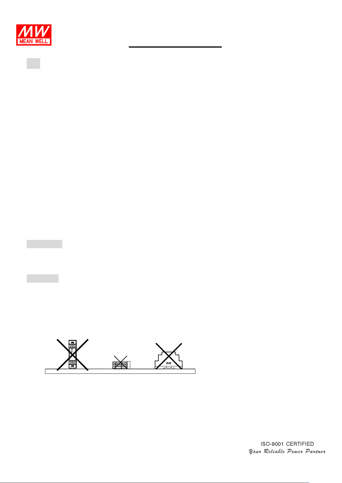
(2)The appropriate mounting orientation for the unit is vertical, the input terminals at the bottom and output on
the top. Mounting orientations other than that, such as upside down, horizontal, or table-top mounting, is not
allowed.
2022.06.28
Installation Manual
3
1
2
4
(3)Use copper wire only, and recommended wires are shown as below.
AWG
18
16
14
12
Rated Current of
Equipment (Amp)
6A 6-10A 13-16A 16-25A
Cross-section of
Lead(mm
2
)
0.75 1.00 1.5 2.5
Note
:
Current each wire carries should be de-rated to 80% of the current suggested
above when using 5 or more wires connected to the unit.
Make sure that all strands of each stranded wire enter the terminal connection and the screw terminals are
securely fixed to prevent poor contact. If the power supply possesses multi-output terminals, please make
sure each contact is connected to wires to prevent too much current stress on a single contact.
(4)Use wires that can withstand temperatures of at least 80°C such as UL1007.
(5)Recommended wire strapping length is 6.5mm (0.255”).
(6)Recommended screwdriver is 3mm, slotted type.
(7)The recommended torque setting for terminals is 5.8 kgf-cm (5.0 Lb-in).
(8)Suggested fuse and maximum number of the MDR PSUs that can be connected to a circuit breaker at 230V are
shown as below.
Model Fuse
Circuit breaker
C16
D16
MDR-10 T2A/L250V 11 22
MDR-20
T2A/L250V
9
18
MDR-40 T2.5A/L250V 6 13
MDR-60 T2.5A/L250V 4 9
MDR-100
T4A/L250V
10
13
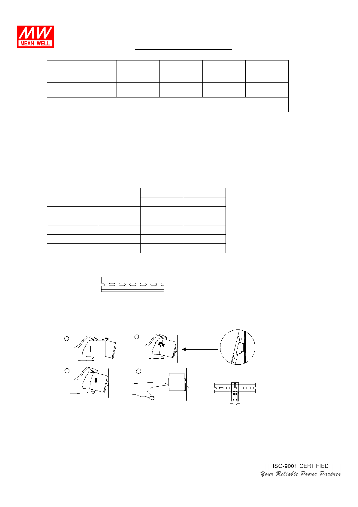
(9)Mounting Instruction:
Mount as shown in figure only, with input terminals down, or else sufficient cooling will not be possible.
Admissible DIN rail:TS35/7.5 or TS35/15
For rail fastening:
(a)Tilt the unit slightly rearwards.
(b)Fit the unit over top hat rail.
(c)Slide it downward until it hits the stop.
(d)Press against the bottom for locking.
(e)Shake the unit slightly to check the locking action.
(10)For other information about the products, please refer to www.meanwell.com
for details.
"Click"

Installation Manual
Warning / Caution !!
(1) Risk of electrical shock and energy hazard. All failure should be examined by a qualified technician. Please do
not remove the case of the power supply by yourself!
(2) Risk of electric arcs and electric shock (danger to life). Connecting both the
primary and the secondary sides
together is not allowed.
(3) Risk of burn hazard. Do not touch the unit in operation and shortly after disconnection!
(4) Risk of fire and short circuit. The openings should be protected from foreign objects or dripping liquids.
(5) Only install the unit in a pollution degree 2 environment (Note.1).
(6) Please do not install the unit in places with high moisture or near the water.
(7) The maximum operating temperature is 35°C for MDR-100-12 and 40°C for MDR-100-24, MDR-100-48 and
50°C for MDR-10/20/40/60 series, please do not install the unit in places with high ambient temperature or
near fire source.
(8) The FG ( ) must be connected to PE (Protective Earth).
(9) Output current and output wattage must not exceed the rated values on its specification.
(10)Disconnect system from supply voltage:
Before commencing any installation, maintenance or modification work: Disconnect your system from
supply voltage. Make sure that inadvertent connection in circuit will be impossible!
(11)For continued protection against risk of fire, replace only with same type and rating of fuse.
Pour ne pas compromettre la protection contre les risqué d’incendie, remplacer par un fusible de même
type et de memes caractéristiques nominales.
Note.1: Pollution Degree 2 applies where there is only non-conductive pollution that might temporarily become
conductive due to occasional condensation. Generally refer to dry, well-ventilated locations, such as
control cabinets.