Machine Control.pdf - 第28页
MACHINE CONTROL CAN BUS 7.28 Technical Reference Manu al Chapter Issue 3 Jan 08 CAN BUS The Controller Area Network (CAN) is a bus system for machine motion control. An encoder/decoder for the 500Kbit/s rate CAN serial l…
MACHINE CONTROL
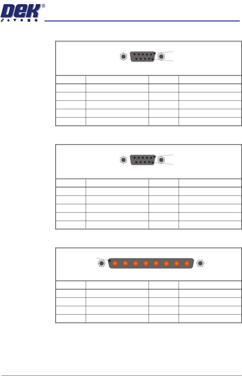
M36 MACHINE CONTROL ENCLOSURE
Chapter Issue 3 Jan 08 Technical Reference Manual 7.27
M36SK24 (X Rear Actuator)
M36SK25 (Y Actuator)
M36PL26 (High Current DC In)
Pin No. Signal Pin No. Signal
1CH2 B- 6N/C
2N/C 7CH2 A+
3CH2 B+ 8N/C
4N/C 9N/C
5CH2 A-
Pin No. Signal Pin No. Signal
1CH1 B- 6N/C
2N/C 7CH1 A+
3CH1 B+ 8N/C
4N/C 9N/C
5CH1 A-
Pin No. Signal Pin No. Signal
1 +12V 5 +24V US
20V Return 60V Return
3 +24V SW (Belt Motors) 7 +24V SW (Stepper Motors)
40V Return 80V Return
9 Way D Type Socket
1
6
9 Way D Type Socket
1
6
8 Way Power D Type Plug
1
MACHINE CONTROL
CAN BUS
7.28 Technical Reference Manual Chapter Issue 3 Jan 08
CAN BUS
The Controller Area Network (CAN) is a bus system for machine motion control.
An encoder/decoder for the 500Kbit/s rate CAN serial link is fitted to the
NextMove ES card to enable communication with the CAN Nodes. The CAN is
a 2-wire data link designed for transmission of small data packets for fast update
of axis position information.
The CAN Bus connects the NextMove ES card to the Nodes that provide
machine motion, switch functions and sensor feedback. There are two different
types of Nodes:
• I/O Node Boards
• Servo/Stepper Nodes
For the CAN Bus to work correctly, the CAN Bus must be terminated using a
CAN Terminator. The CAN Terminator is fitted to the output connector of the
last node in the CAN Bus line and consists of a 9 pin D type connector with a
link resistor fitted inside the connector hood.
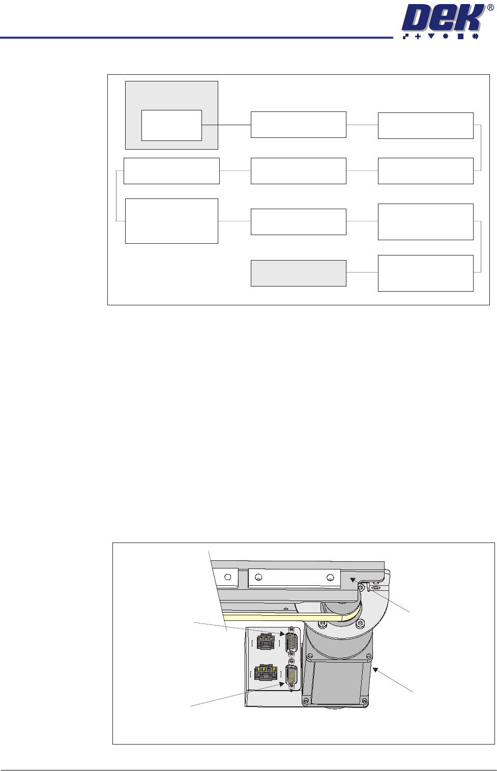
Figure 7-7 CAN Terminator Connection
M36 Machine
Control Enclosure
NextMove ES
(I/O Node 1)
Servo Node 6
Rising Table Motor
Stepper Node 10
Paste Dispense Motor
I/O Node 3 Board
Print Carriage I/O
Servo Node 7
Print Carriage Motor
I/O Node 2 Board
Main Machine I/O
I/O Node 4 Board
Screen Cleaner I/O
Stepper Node 15
Pass Through Rail
Width Motor
(Dual Lane Only)
CAN Terminator
CAN Bus
Servo Node 8
Camera X Motor
(Rotary Motors Only)
Servo Node 9
Camera Y Motor
(Rotary Motors Only)
Camera X Motor
(Servo Node 8)
Camera CarriageConnector for
CAN Terminator
Connector for
CAN Bus Input
View on Front Right of Camera Carriage (Rotary Motors Only)
MACHINE CONTROL
CAN BUS
Chapter Issue 3 Jan 08 Technical Reference Manual 7.29
I/O Node Boards
CAUTION
ANTI-STATIC HANDLING. STANDARD PRECAUTIONS MUST BE ADHERED TO
WHEN HANDLING ELECTRONIC CARDS AND CONFIGURING AND INSERTING
INTO THE ENCLOSURES.
The I/O Node Boards consists of multiple inputs and outputs, CAN encoder/
decoder and multi-way connectors for machine components.
There are three I/O Node Boards fitted to a standard machine with a possible
one other board for the underscreen cleaner, if fitted, these are:
• I/O Node 1 - NextMove ES card (CAN master) located in the M36 Machine
Control Enclosure (standard)
• I/O Node 2 - Main Machine I/O board located at the rear of the machine
(standard)
• I/O Node 3 - Print Carriage I/O board located inside the print carriage
extrusion (standard)
• I/O Node 4 - Screen Cleaner I/O board located at the rear of the machine
(optional)
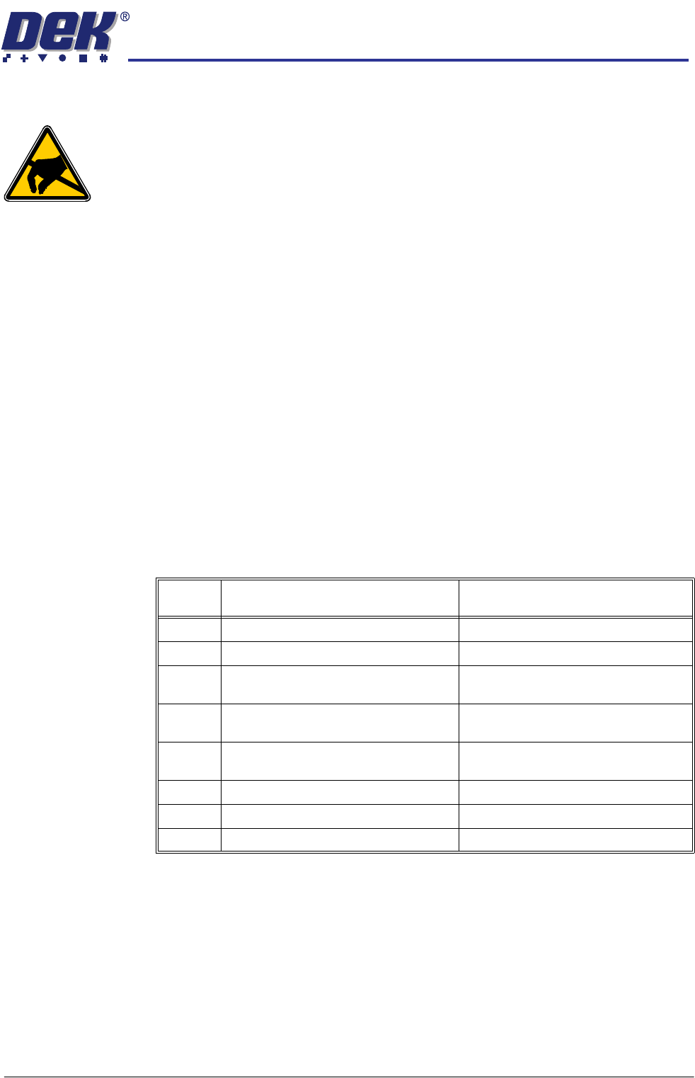
I/O Nodes 2 & 4 have a green (status) and a red (error) LED mounted on the
board. The status LED should flash twice periodically and the error LED should
not be illuminated during normal operation. The following table describes other
operations of the LEDs:
I/O Node 1 I/O Node 1 is the CAN master and is also known as the NextMove ES card
housed in the M36 Machine Control Enclosure. For more information, refer to
the M36 Machine Control Enclosure - NextMove ES Card section of this
chapter.
No of
Pulses
Red (error) LED Green (status) LED
Static Off No error Initialisation/Code execution stopped
1 Node ID from DIP switches is 0 CANopen NMT state is ‘pre-operational’
2 EEPROM contents invalid (EEPROM
empty/checksum error)
CANopen NMT state is ‘operational’
3 EEPROM access impossible (hardware
error)
CANopen NMT state is ‘stopped’
4 CAN controller switched to ‘bus-off’
mode
N/A
5 Firmware error N/A
6 Controller overload N/A
Static On Severe hardware/software error N/A