Machine Control.pdf - 第48页
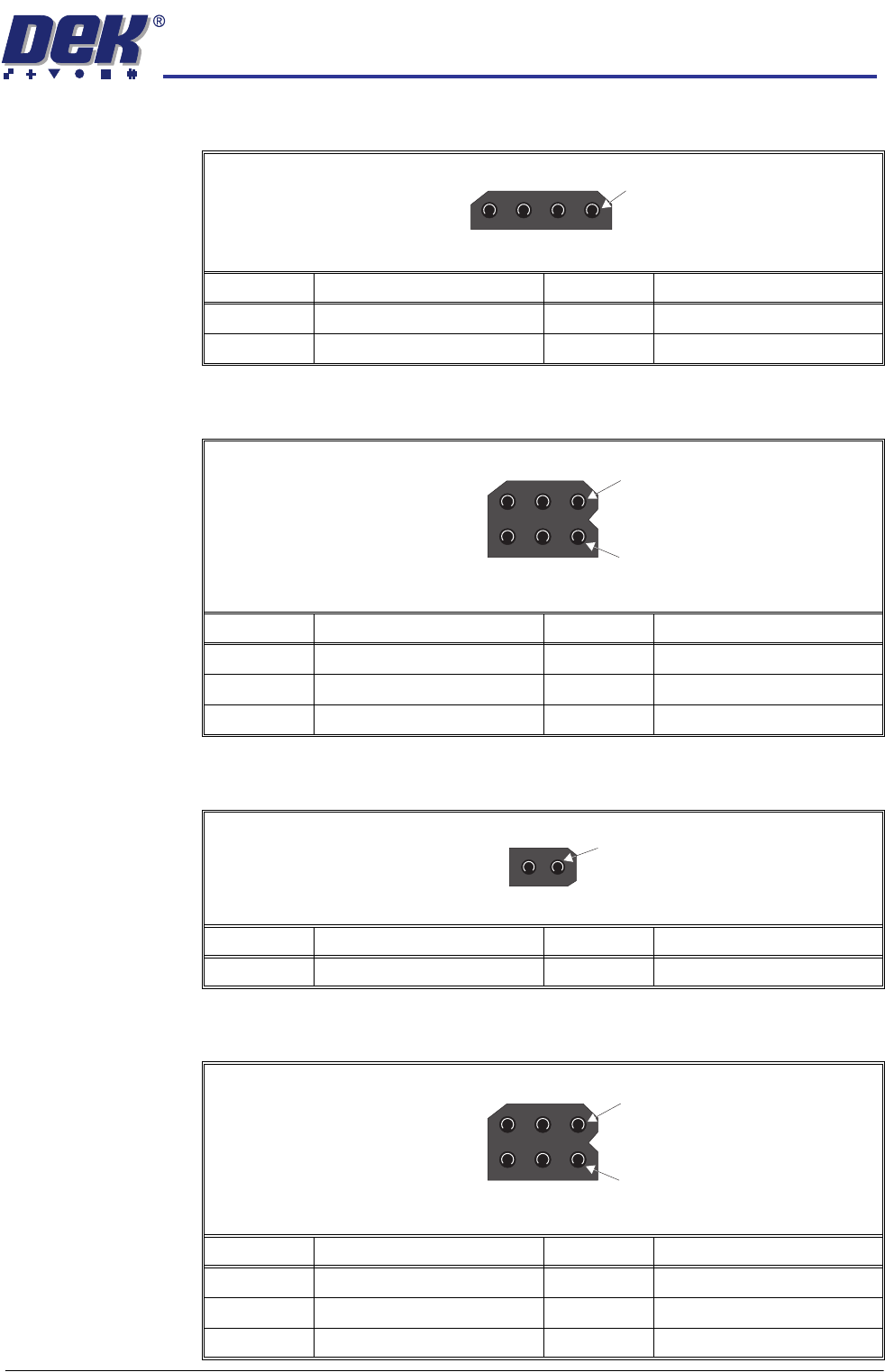
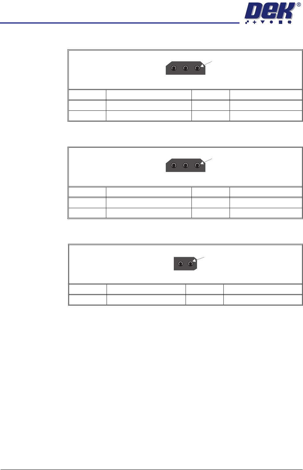
MACHINE CONTROL CAN BUS 7.48 Technical Reference Manu al Chapter Issue 3 Jan 08 N4SK13 N4SK14 N4SK15 Pin No. Sig nal Pin No. Signal 1 +12V 3 0V 2 S pare Input 1 3 W ay T rident Connector Pin No. Sig nal Pin No. Signal 1 …
MACHINE CONTROL
CAN BUS
Chapter Issue 3 Jan 08 Technical Reference Manual 7.47
N4SK9
N4SK10
N4SK11
N4SK12
Pin No. Signal Pin No. Signal
1 Spare Output 3 Spare Output
20V 40V
1
4 Way Trident Connector
Pin No. Signal Pin No. Signal
1 +12V 4 +12V
2 Board Present 5 Product Sensor
30V 60V
4
1
6 Way Trident Connector
Pin No. Signal Pin No. Signal
1 Oscillating Motor 2 0V
2 Way Trident Connector
1
Pin No. Signal Pin No. Signal
1 +12V 4 +12V
2 Cleaner Dropped 5 Spare Input
30V 60V
4
1
6 Way Trident Connector
MACHINE CONTROL
CAN BUS
7.48 Technical Reference Manual Chapter Issue 3 Jan 08
N4SK13
N4SK14
N4SK15
Pin No. Signal Pin No. Signal
1 +12V 3 0V
2 Spare Input
1
3 Way Trident Connector
Pin No. Signal Pin No. Signal
1 +12V 3 0V
2 Spare Input
1
3 Way Trident Connector
Pin No. Signal Pin No. Signal
1 Cleaner Camera Clamp 2 0V
2 Way Trident Connector
1
MACHINE CONTROL
CAN BUS
Chapter Issue 3 Jan 08 Technical Reference Manual 7.49
Servo/Stepper
Nodes
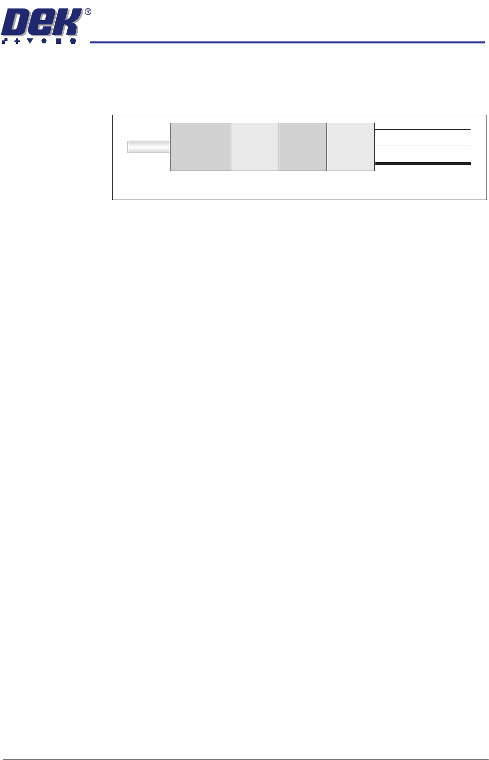
These nodes can be either servo or stepper motors with built in sensors,
controller, drive electronics and CAN encoder/decoder. The motor is connected
to the CAN Bus allowing direct communications with the NextMove ES card in
the M36 Machine Control Enclosure.
The following motors are fitted to all machines:
• Servo Node 6 - Rising Table Motor
• Servo Node 7 - Print Carriage Motor
The following motors may be fitted dependant on machine options and variants:
• Servo Node 8 - Camera X Motor (rotary drive machines only)
• Servo Node 9 - Camera Y Motor (rotary drive machines only)
• Stepper Node 10 - Paste Dispenser Motor (optional)
• Stepper Node 15 - Pass Through Lane Rail Width Motor (Dual Lane only)
NOTE
For further information on the servo/stepper motors above, refer to the relevant
chapter of this manual.
Servo/Stepper
Motor
(Brushless)
Drive
Electronics
Processor
CAN
Encoder/
Decoder
CAN Bus In
CAN Bus Out
DC Supply In
CAN Motor Block Diagram