MAN00000772_SI-G200BB_SVCPDFA.pdf - 第685页
C h an ge P ro c edu re fo r R T axis T i m i ng B elt 4 Remo ve th e rotary e nc o der. Refer to RPGB- 10701-1 1. Adjust the positio n as shown in fi gure. 2. Apply marking –o ff l ine to th e e ncoder . 5 T ake o ut th…
Change Procedure for RT Axis Timing Belt
Change Procedure for RT Axis Timing Belt
[Necessary Jigs]
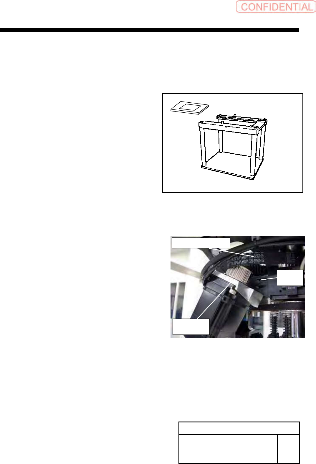
Head block
Tension Meter (UNITTA U-507)
Belt Tension JIG
[Disassembly]
1
For the removal procedure for the head unit refer to
RPGB-10301-1
The following procedure is designed for the work on the
head block.
2
Remove the screws (2-C4x18), tilt the RT axis motor bracket.
Refer to RPGB-10601-1 _ 5
3
Remove the RT axis timing belt from the pulley on the motor side.
Change Procedure for RT-axis
Timing Belt
SHEET
1/3
RPGB-10901-1
RT Axis motor
bracket
C
4
x
18
W4
RT Axis timing belt
Change Procedure for RT axis Timing Belt
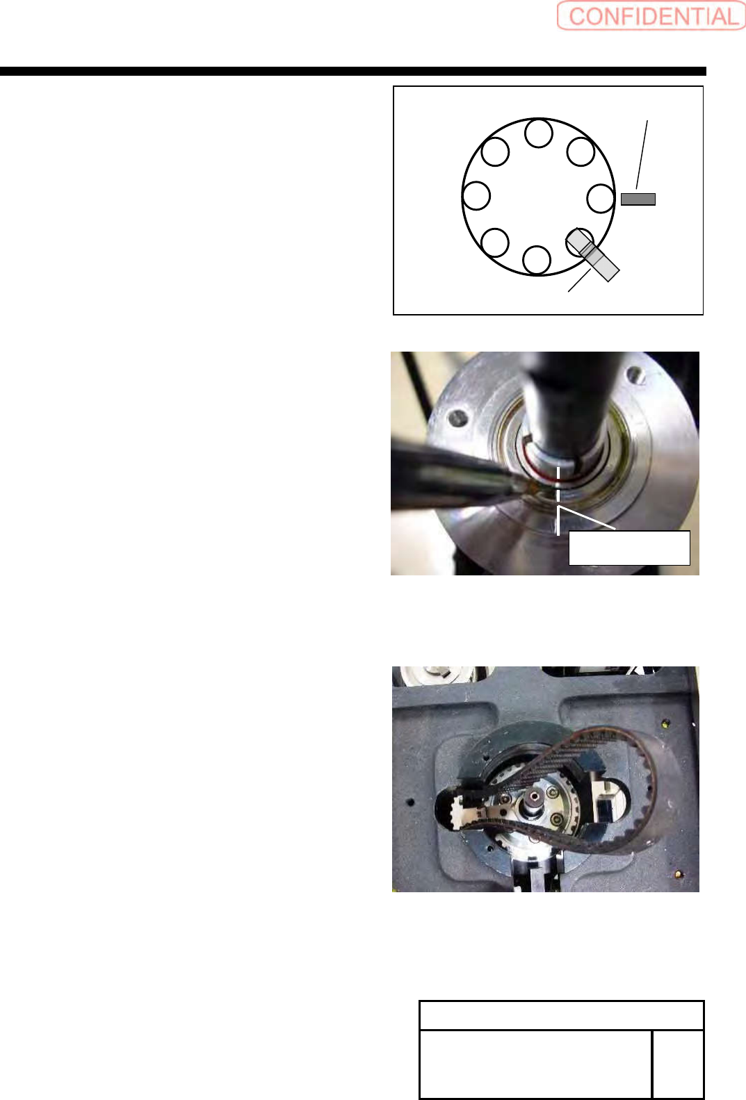
4
Remove the rotary encoder. Refer to RPGB-10701-1
1. Adjust the position as shown in figure.
2. Apply marking –off line to the encoder.
5
Take out the timing belt from upper side of
the head base.
Change Procedure for RT-axis
Timing Belt
SHEET
2/3
RPGB-10901-1
Marking
-
off line
Line
RT dog
RT ORG sensor
1
8
7
6
5
4
3
2
Change Procedure for RT-axis Timing
Belt
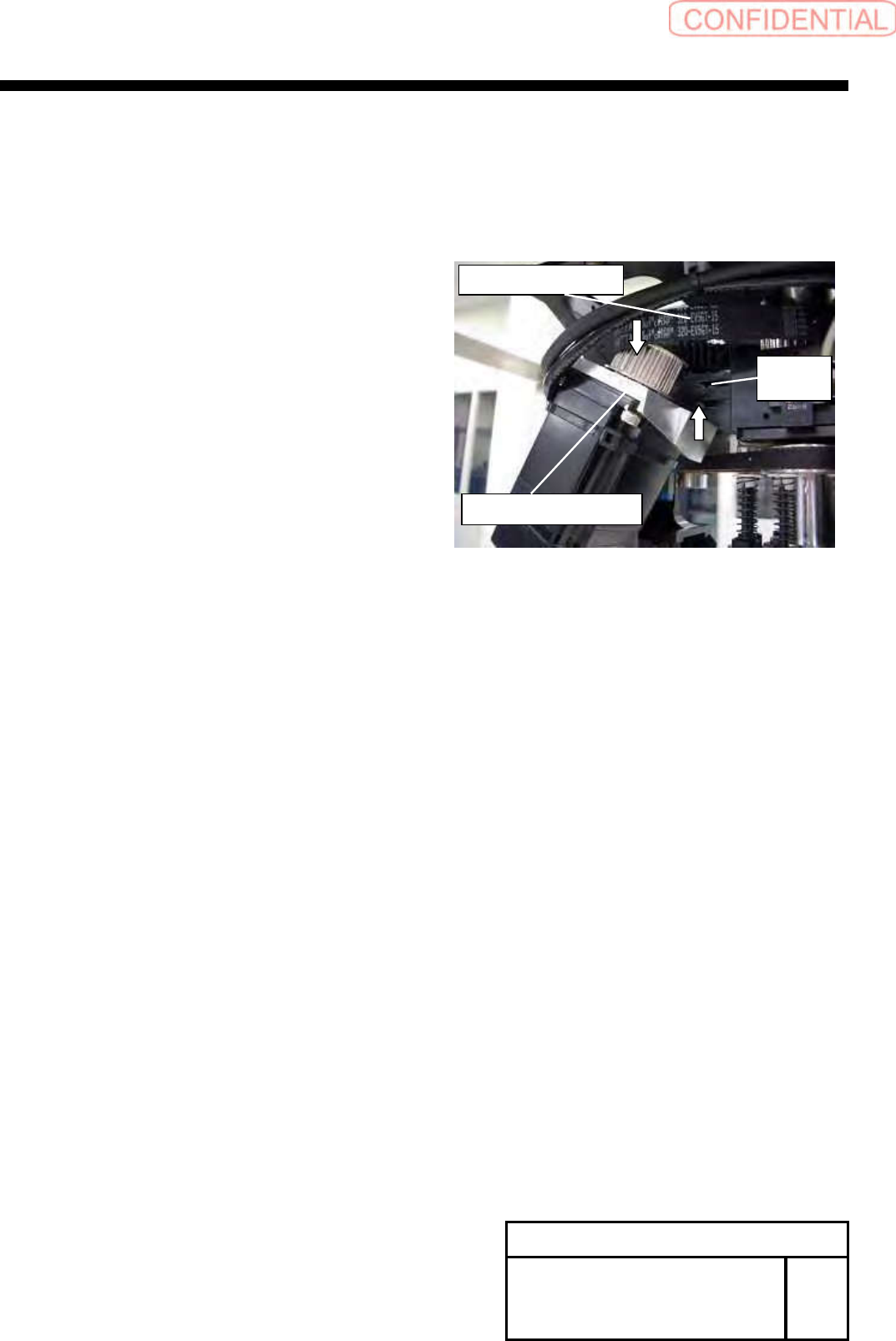
[Reassembly]
6
Install the new timing belt from upper side of the head base.
7
Attach the rotary encoder.
1. Refer to RPGB-10701-1
8
Apply the RT axis timing belt to the pulley on the motor side.
9
Temporarily tighten with the screws (2-C4x18) from the
rear side the H axis motor bracket.
10
Adjust the belt tension.
Refer to PGB-10601-1.
11
Install the head unit to the main body.
Refer to PGB-10301-1
[Adjustment]
12
Calibration
1.HLGB-10201-01 Machine Setup
2.HLGB-10304-01 Calibration
Change Procedure for RT-axis
Timing Belt
SHEET
3/3
RPGB-10901-1
RT axis Motor Bracket
C
4
x
18
W4
RT axis Timing Belt