ASM贴片机 X 系列机型电路图.pdf - 第202页
2 - 132 ZTH041_ X3X4- 010202LD3 Z1-Achse, TwinHead, P&P-Mo dul 1, Por tal 4, SIPL ACE X3/X 4 (Bl. 3 v . 3) Z1 axis, T winHead, P&P module 1, gantry 4, SIPLACE X3 /X4 (sh. 3 of 3) (W5) (W5) (W5) (W3) (W3) (W3) 1 B…
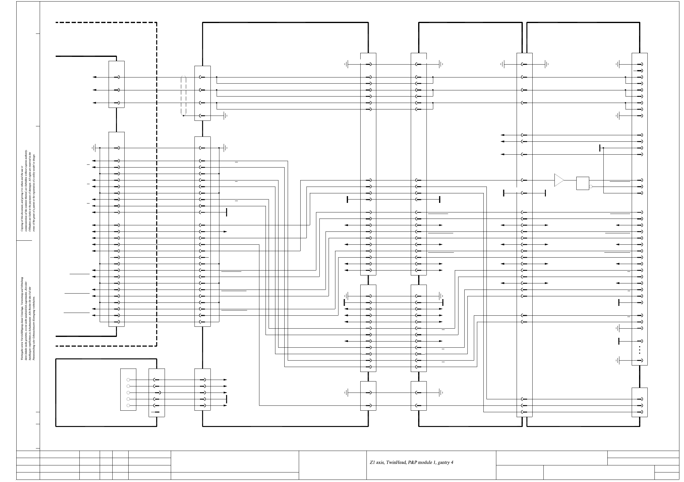
2 - 131
ZTH041_X3X4-010202LD3 Z1-Achse, TwinHead, P&P-Modul 1, Portal 4, SIPLACE X3/X4 (Bl. 2 v. 3)
Z1 axis, TwinHead, P&P module 1, gantry 4, SIPLACE X3/X4 (sh. 2 of 3)
PE
Key
3
4
5
1
2
X31dr
34-pole34-pole
34-pole 34-pole
34-pole34-pole 140-pole
50-pole
GND
03057572
01.
02.
02.
Status
Function status
Revision status
Document status
Modified Date Name
Date
Author
Check.
Stand.
Mat.no.:
CAD file:
Orig./Repl.f./Repl.by
Sh.
Sh.(s)
09.03.08
04.03.09
17.02.11
09.03.2008TDH
TDH
TDH
TDH
ZTH041_X3X4-010202LD3_SH02.DWG
Copyright ©
ASM Assembly Systems
GmbH & Co. KG
Z1-Achse, TwinHead, P&P-Modul 1, Portal 4
SIPLACE X3/X4
SIPLACE X-Series
ZTH041_X3X4-010202LD3
2
3
Z1-Force-DATA
Z1-Force-DATA
Carrier cable 8, 2GE
03052298
DP1/DP2 motor
30
X8da
33
32
+24V
29
28
+15V
26
27
25
Z1 track B30
X8dc
33
32 Z1 track A
Z1 track A
29
28
26
27
25
Z1 track B
+24V
Z1 track N
Z1 track N
+15V
03052296
Carrier cable 6, 2GE
S/Z2 motor
1,10,34
+5V
-15V
GND
19
22
16,31
PE
X6da
+15V 25
+24V 28
23
24
19
22
16,31
X6dc
1,10,34
+5V
-15V
GND
PE
25
28
23
24
+15V
+24V
31
+24V +24V84,86
35
37
33
39
44
88,90
41
46
+15V
+15V
X30dr
Z1 reference point
Z1 temperature sensor
Z1 clamping
24
23
21
PE 50
Z1 track A
PE
34
35
33
Z1-Force-DATA
Z1-Force-DATA
+24V
28
Z1 track A
GND
Z1 track B
Z1 track B
32
31
29
30
+15V
Z1 track N
Z1 track N
25
26
27
23
24
Z1-Force-CS
Z1-Force-CS
Z1-Dir
Sheet 3
Z1 track A
3
Z1 reference point
Z1 temperature sensor
+5V
Z1 track N
Z1 track N
Z1 track B
OPTO_GND
Z1 track B
Sheet 3
9
13
10
12
11
6
8
7
5
4
Z1 track A
Axis unit
03048879 (tq)
Backplane
X1vp /
X08_1tq
PE 1
2
26-pole
Phase_W 3BN
X08_3tq
1Phase_U
Phase_V
2
WH
GN
Axis unit
Z1 reference point
Z1 temperature sensor
Z1 track A3
Z1 track N9
11
13
12
10
+5V
GND
6
8
7
5
4
Z1 track B
Z1 track N
Z1 track B
BK
BN
03009834
Actual value
Z1 axis
1PE
2
X24da
Z1 track A
Z1 motor W
4PE
3
Cable carrier interface
WH
GN
Z1 motor
03050914
Z1 motor U
Z1 motor V
1
2
X14da
Gantry 2 or 4
Cable carrier interface
03010622 (da)
-15V -15V22 22 -15V-15V 87,89 -15V 22
1,10,14,34PE PE1,10,14,34
15 15 Z1 clamping
60
81
68
Z1 reference point
Z1 temperature sensor
Z1-Force-SCLK
Z1-Force-SCLK
+5V 19
21
20
18
17
14
GND
16,31
15
12
19
21
20
18
17
+5V
Z1-Force-CS
Z1-Force-CS
14
16,31
15
12
GND
Z1-Dir
6
7
5
6
7
5
Z1 motor W
GND
48
50
58
56
83,85VCC
VCC
7,13,134,140
62
GND
Z1-Dir
X13cc:73
X14cc:71
X14cc:73
133
135
1
95,97
03052297
Carrier cable 7, 2GE
Z1/DP1 motor
1,8,9,10,34
2
3
4
PE
X7da
1,8,9,10,34
2
3
4
X7dc
Z1 motor U
Z1 motor V
PE
03000901 (dc)
Head interface
Gantry 4
91,92
103,105
X22dc/J3
99,101
PE PE
Z1-Force-SCLK
Z1-Force-SCLK
U2
U1
1
I1
3
2
VCC
Z1-Force-CS
Z1-Force-CS
19
21
20
18
17
Z1-Force-Dir
Z1-Force-Dir
15
16
14
Gantry-ID-Bit 2
Gantry-ID-Bit 1
Gantry-ID-Bit 0
GND
Power failure
12
13
11
10
PE
Z1 motor W
9
7
8
6
From sheet 1
P&P head adapter
03000902 (dr)
Z1 motor U
Z1 motor V
Z1 clamping1414
Sub-distributor
+15V
03046226 (ra)
0V
+5V
Z1-Force-DATA
-15V
+24V
X1ra
26
Z1 clamping
Z1-Dir
Z1-Force-DATA
Z1-Force-SCLK
Z1-Force-SCLK
Z1-Force-CS
Z1-Force-CS
20
22
21
25
24
23
19
17
18
16
15
n.u.
+15V
3GN3(W1)RD
6
Key
PK
WH
5
4
n.u.
(W2)
(W2)
2
1
5
4
GND
+5V
Z1-Force-SCLK
Z1-Force-SCLK
Z1-Force-DATA
Z1-Force-DATA
Cable carrier interface
X6ra
BU
OG
2
1
(W1)
(W1)
BN
WH
Voltage
03009828
X50da
2
1
-15V
+24V
26
20
24
25
23
21
22
17
18
19
15
16
n.u.
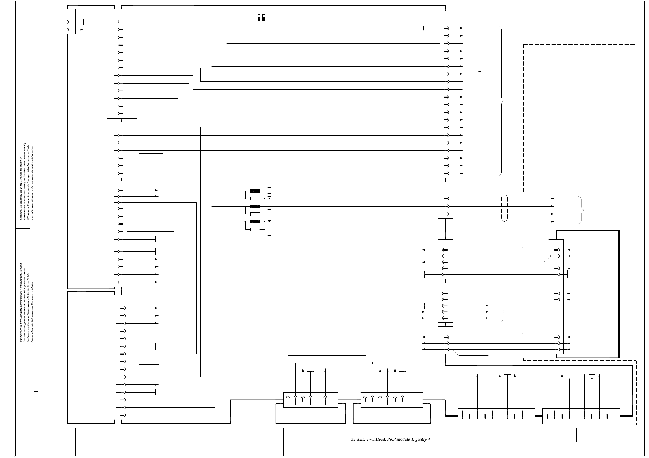
2 - 132
ZTH041_X3X4-010202LD3 Z1-Achse, TwinHead, P&P-Modul 1, Portal 4, SIPLACE X3/X4 (Bl. 3 v. 3)
Z1 axis, TwinHead, P&P module 1, gantry 4, SIPLACE X3/X4 (sh. 3 of 3)
(W5)
(W5)
(W5)
(W3)
(W3)
(W3)
1
BN
3
2
WH
GY
4
5
3
GN
WH
BN
(W1)
(W1)
(W1)
(W2)
(W2)
(W1)
(W1)
42
1
2
5
2
1
GNYE
1
3
2
1
4
3
Vin(+)_AXIS
POWER_FAIL_24VDC
POWER_FAIL_AXIS
SERVO_ENABLE
11
2
10
GND_Z/DP
Vin(-)_AXIS
+150V_Star
+40V_Z/DP
7
9
6
3
4
1
Power supply
00354626
WH+BN (W4)
EMERG.-STOP_MAIN_AXIS
Z2 motor_W
Screen
Z2 motor_U
Z2 motor_V
03050914
X14da
Sheet 2
WH
GN
BN
BK
X45tq
X46tq
X47tq
03050920
X4ra:3
X4ra:2
X4ra:1
X4ra:1
Main distributor 03046226
Main distributor 03046226
X14
01.
02.
02.
OFF
ON
S1
12
26-pole
6
12
13
14
10
9
8
3
5
2
X1vp /
03048879 (tq)
Backplane, axis unit
1,4,7,17,20,23,26
PE
(S1.2 n.u.)
11
A/D22; B/E22,24,25; C20,25
C23
B/E18
C12
C13
E13
D13
E15
D14
E14
X22_3tq
D15
X3tb
C16
D16; E17
D17
D24
E19
D19
D25
A/C/E3,4,7,8,11
E16
B/D1,2,5,6,9-11
Axis unit
X08_2tq
A/C32
A/C30
C26; A/C28
C10
C18; A/C20
C14
C12
A12
A8
C8
A/C2
C4
A4
X1tq
GND
AGND
-15V
+15V_Servo
+5V
X4tb
C1
C5
AGND End signal
22
X22_3tqX3tb
24
25
R28
R30
L15
L13
R29
L14
A24
E25
E24
A25
X22_2tqX2tb
D23
D22
Act. value, Z1 axis
Z1-Dir
Z1-Force-CS
Z1-Force-CS
n.u.
Z1-Force-DATA
Z1-Force-DATA
Z1-Force-SCLK
Z1-Force-SCLK
PE
Z1-Force-SCLK
Z1-Force-DATA
Z1-Force-DATA
Z1-Force-CS
Z1-Force-CS
Z1-Force-SCLK
Z1 temperature sensor
Z1 reference point
Z1 clamping
Z1-Dir
+5V
I²t
03057572
Gantries 1 and 4
B12, C17
C14, C18 POWER_FAIL, X47tq:2
+15V, EMERG_STOP_HEAD_AXIS
POWER_FAIL_24VDC
POWER_FAIL
+15V
-15V
PGND
Vin(+)Axis
Vin(-)Axis
PGND
+150V_Star
+40V_Z/DP
03036027 (tb)
Axis card A364, gantry 3 SDS60/3Z1 servo amplifier
03002141 (tq)
Z1 track A
Z1 track A
Z1 track B
Z1 track B
Z1 track N
Z1 track N
OPTO_GND
UB_Power_OK
Inom_W
Inom_U
+15V_Servo
-15V_Servo
Servo_Ready
AGND
Inom_W
Inom_U
Servo_Enable
+40V_Z/DP
UB_Power_OK
+150V_Star
Phase_V
Phase_U
Phase_W
C15
Servo_Enable
Servo_Ready
PGND
C22; A/C24
C16 I²t
1
2
3
WH
GN
BN
Phase_U
Phase_V
Phase_W
D22
+15V_Servo
-15V_Servo
+5V
+15V
-15V
D10,18
D30
Z28
Z20;D22
Z4; D6
D30
D10
Z28
Z16;D18
D6
8
X30_1tq
1
3
2
4
5
6
7
Powerfail_24VDC
PA1_CAN_L
GND
PA1_CAN_H
9
n.u.
n.u.
n.u.
n.u.
9
n.u.
1
5
n.u.
n.u.
7
8
6
n.u.
3
4
2
X30_2tq
PA2_CAN_H
PA2_CAN_L
Powerfail_24VDC
GND
DC/DC converter 5V/±15V
00353449
DC/DC converter ±15V
00353450
X51tq
X50tq
Z4,8,20
Z8,16
GND
AGND
X08_1tq
X24da
Sheet 2
03009834
X08_3tq
+5V
Z1 reference point
Z1 clamping
Z1 temperature sensor
OPTO_GND
Z1 track A
Z1 track A
Z1 track B
Z1 track B
Z1 track N
Z1 track N
C22 +15V
D18
C21
15
21
19
16
18
Status
Function status
Revision status
Document status
Modified Date Name
Date
Author
Check.
Stand.
Mat.no.:
CAD file:
Orig./Repl.f./Repl.by
Sh.
Sh.(s)
09.03.08
04.03.09
17.02.11
09.03.2008TDH
TDH
TDH
TDH
ZTH041_X3X4-010202LD3_SH03.DWG
Copyright ©
ASM Assembly Systems
GmbH & Co. KG
Z1-Achse, TwinHead, P&P-Modul 1, Portal 4
SIPLACE X3/X4
SIPLACE X-Series
ZTH041_X3X4-010202LD3
3
3
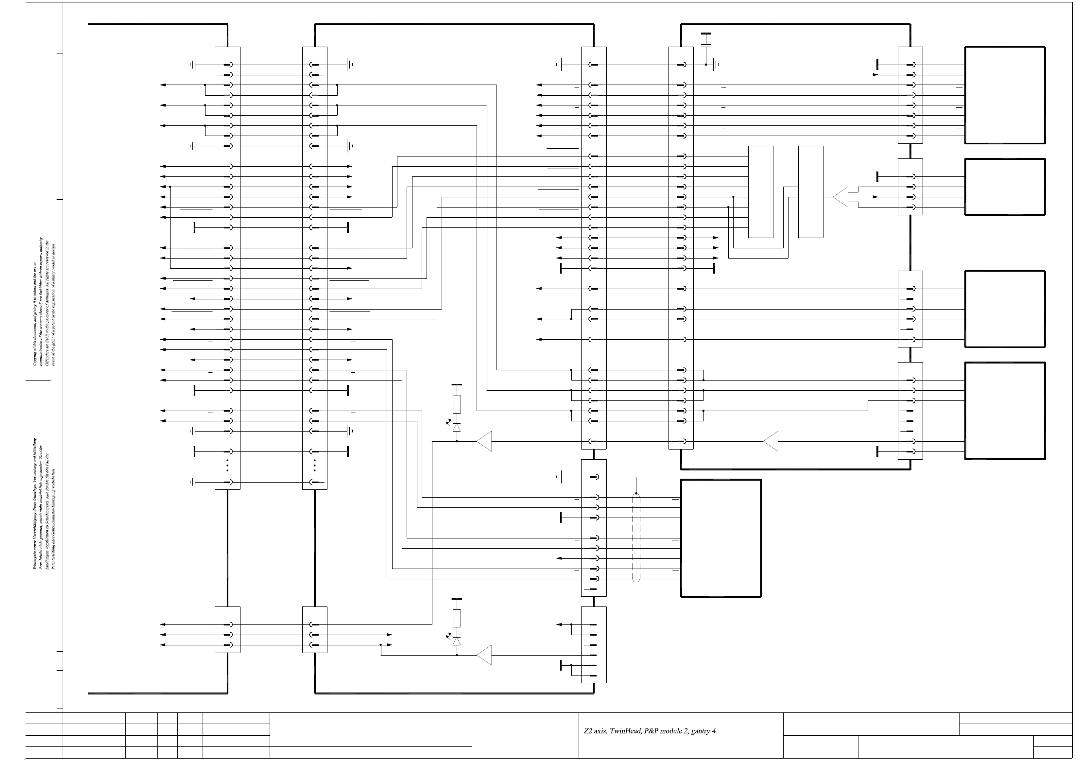
2 - 133
ZTH042_X3X4-010202LD3 Z2-Achse, TwinHead, P&P-Modul 2, Portal 4, SIPLACE X3/X4 (Bl. 1 v. 3)
Z2 axis, TwinHead, P&P module 2, gantry 4, SIPLACE X3/X4 (sh. 1 of 3)
X30dd:27
X30dd:26
X30dd:29
X30dd:33
+5V 1
GND 5
6
4
2
Key
3
Scanning head
03000102
Z2 axis
Z2 temperature sensor
Z2 motor W
Z2 motor V
10
X5dd
Key
Z2 track N
Z2 track N 9
8
BN
GY
Z2 track B
Z2 track B 6
7
5
Z2 track A
4
3
PK
RD
BK
YE
WH
RI
RI
GND
+5V
T2
T2
T1
30
X4dd
PE 1
Z2 track A 2
WHGN
GN
Z2 motor W
Z2 motor V
29
27
28
26
30
T1
29
27
28
26
BN7
GND 8 YE
Key
Key
Key
6
5
3
4
2
BU
GY
Temperature sensor
00353135
Z2 axis
Linear drive
Linear motor
U-Sensor
C700 TwinHead force meas. board, P&P module 2
Z2 motor U
DP2 motor W
DP2 motor V1
DP2 motor V2
DP2 motor U
GNDGND 1919
Z2 motor U 24
25
23
21
22
20
24
25
23
21
22
20
13
-15V
+5V
+15V
16
18
17
15
14
10
12
11
9
8
13
-15V16
18
17
+5V
+15V
15
14
10
12
11
9
8
2
3
6
2
1
9
7
10
14
15 J13
-
1
J12
+
DP2 track B
DP2 track B
DP2 track A
DP2 track A
DP2 track N
DP2 track N
Force sensor
DP unit control cable
03005289
DP2 track B
DP2 track N
DP2 track N
DP2 track B
DP2 track A
5
7
6
4
3
X8dd
DP2 track A
PE
2
1
5
7
6
4
3
X8de
2
1 PE
00352809 (de)
C37
220n
B- (W)
B+ (V)
A- (V)
A+ (U)
X17de
1
Key
1
2
WH
GY
X16de
5
Key
4
3
6
BN
BU
YE
03014681
DISC-Magnetic-Motor
P310.
OUT +
U-Sensor +
OUT -
4
X15de
GND
1
3
2
03000100
Force transducer
RI
RI
T1
T2
T2
GND
+5V
T1
6
8
7
5
4
X18de
+5V
GND
2
3
1
Encoder
03000046
Pick&Place module
U-Sensor -
Key
+5V
GND
50-pole 50-pole
GND
GND
Z2 reference point
DP2 motor U
DP2 motor V
DP2 motor W
Z2 temperature sensor
Z2-Force-SCLK
Z2-Force-SCLK
Z2-Force-Dir
Z2-Force-Dir
Z2-Force-CS
Z2-Force-CS
Z2-Force-DATA
Z2-Force-DATA
21
23
24
X32dr
50
33
34
35
32
31
Z2 temperature sensor
Z2 reference point
Z2 clamping
PE
Z2 track A
PE
Z2 track A
GND
Z2 temperature sensor24
Z2 clamping
Z2 reference point
23
21
D6X2dd:78 green
Twin flat ribbon cable loom
03004332-W3
X30dd
n.u.
35
50
Z2 track A
Z2 track A
34
33
PE
31
32
GND
V1green
30
2
4
5
3
1
7
10
9
8
13
12
15
14
11
16
18
17
19
20
21
23
22
6
24
26
27
25
29
28
X33dr
PE
VCC
Z2 track B
Z2 track B
+24V
Z2 track N
Z2 track N
+15V
Z2-Force-DATA
Z2-Force-DATA
Z2-Force-SCLK
Z2-Force-SCLK
-15V
Z2-Force-Dir
Z2-Force-CS
Z2-Force-CS
GND
Z2-Force-Dir
Gantry-ID-Bit 2
Gantry-ID-Bit 1
Gantry-ID-Bit 0
Power-Fail
P&P head adapter
03000902 (dr)
Sheet 2
Z2 motor W
Z2 motor V
Z2 motor U
Key
PE
PE9
+5V19
Z2 track B
Z2 track B
Z2 track N
Z2 track N
29
30
28
+24V
27
26
25
+15V
Z2-Force-SCLK
Z2-Force-SCLK
Z2-Force-DATA
Z2-Force-DATA
-15V22
23
24
20
21
Z2-Force-Dir14
Z2-Force-CS
Z2-Force-CS
Z2-Force-Dir
17
18
15
16
GND
P&P-Head-ID-Bit
Power-Fail
Gantry-ID-Bit 1
Gantry-ID-Bit 0
11
12
13
10
X30dd:4, 5
X30dd:2, 3
X30dd:6, 7
Twin flat ribbon cable loom
03004332-W4
Z2 motor V
Z2 motor W
6
7
8
4
5
Z2 motor U
X31dd
2
3
1
n.u.
PE
00352833 (dd)
C600 head main board, P&P module 2
X30dd:32
X30dd:30
01.
02.
02.
Status
Function status
Revision status
Document status
Modified Date Name
Date
Author
Check.
Stand.
Mat.no.:
CAD file:
Orig./Repl.f./Repl.by
Sh.
Sh.(s)
09.03.08
04.03.09
17.02.11
09.03.2008TDH
TDH
TDH
TDH
ZTH042_X3X4-010202LD3_SH01.DWG
Copyright ©
ASM Assembly Systems
GmbH & Co. KG
Z2-Achse, TwinHead, P&P-Modul 2, Portal 4
SIPLACE X3/X4
SIPLACE X-Series
ZTH042_X3X4-010202LD3
1
3