Operating Instructions_VF366_en.pdf - 第389页
9|Spare and wear parts Base module 900 1 2 3 4 3 6 3 3 5 Fig.144: EM-113-10-00a Pos Designation Item number A B 1 Lever element 86699 x 2 Adjusting foot 135393 x 3 Gas spring (300 N) * 89801 x 4 Adjusting sheet for so…
9|Spare and wear parts
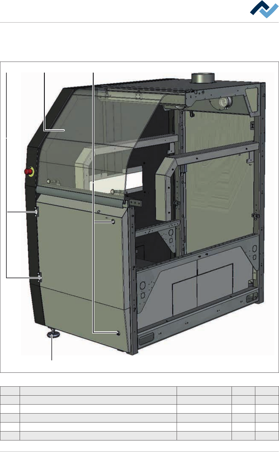
9.2.2 Base Module 900
1 32
4
Fig.143: EM113-10-00
Pos Designation Item number A B
1 Safety glass plate module 900 189028 x
2 Hinge EMKA Type 1110 93324 x
3 Lock 6VER2520 x
4 Adjusting foot 6STELLFM16X155 x
5 Key for control cabinet (unpictured) 6VERSCHLÜ2531 x
Ersa GmbH Operating Instructions_VF366_en|Rev. 14|30/11/2017 388/551
9|Spare and wear parts
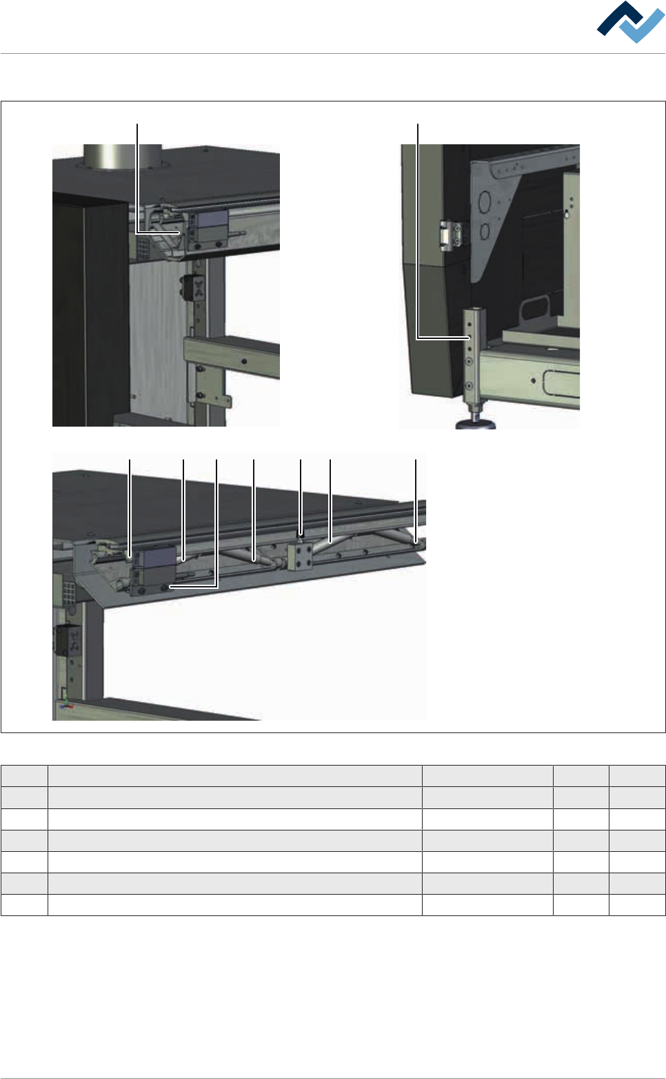
Base module 900
1 2
3 4 3 6 3 35
Fig.144: EM-113-10-00a
Pos Designation Item number A B
1 Lever element 86699 x
2 Adjusting foot 135393 x
3 Gas spring (300 N) * 89801 x
4 Adjusting sheet for solenoid-switch 164880 x
5 Switch holder 163336 X
6 Pressure screw (Neopren) 6GN808-M5-45 X
*Please note the type designation on the gas spring housing! To mount the gas
spring, Assembly tool for gas spring, item 123716 is required! Always have gas
springs replaced by specialised personnel!
Ersa GmbH Operating Instructions_VF366_en|Rev. 14|30/11/2017 389/551
9|Spare and wear parts
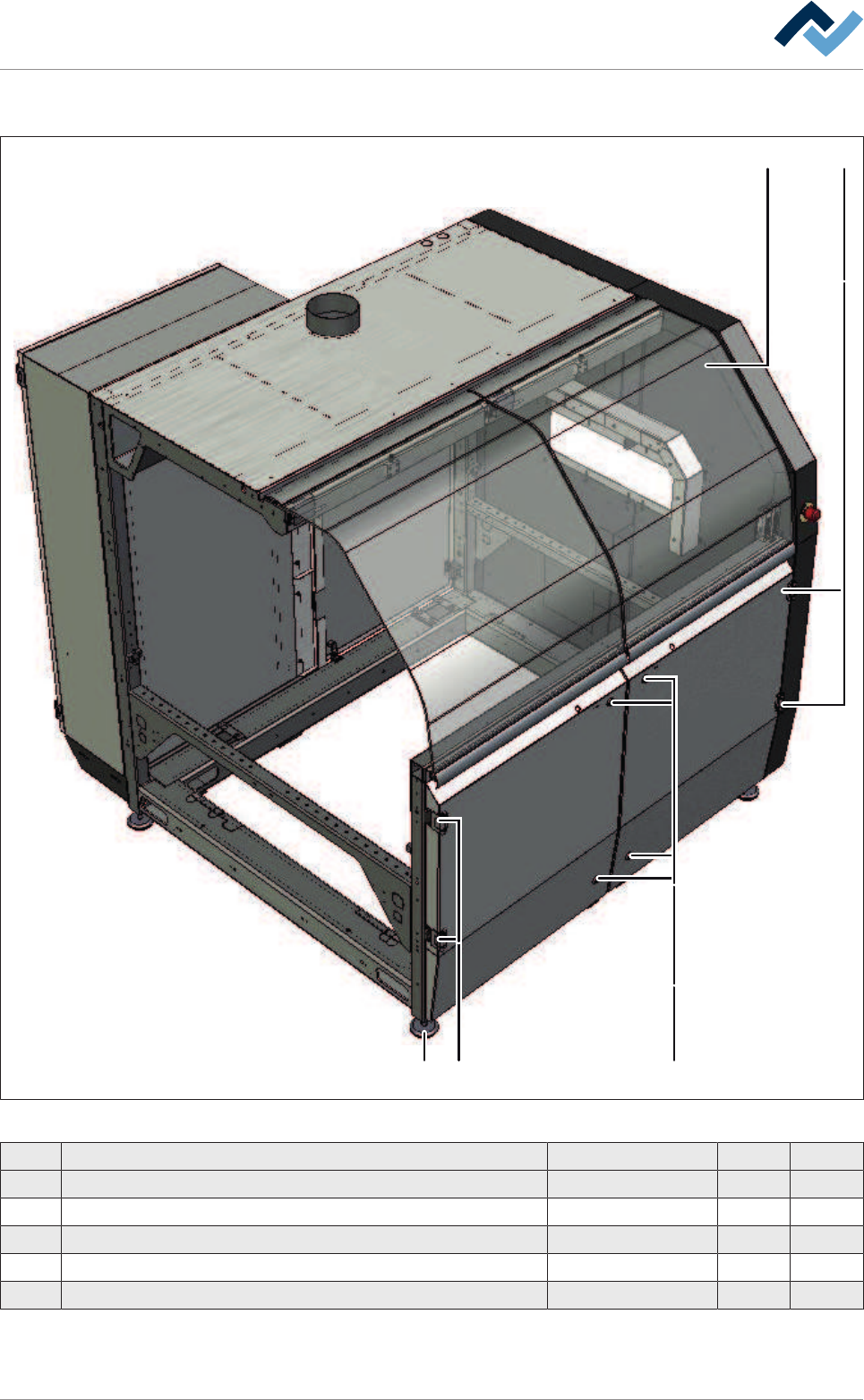
9.2.3 Additional module 1850
1 2
24 3
Fig.145: EM113-15-00
Pos Designation Item number A B
1 Safety glass plate without cutout, module 1100 86292 x
2 Hinge EMKA Type 1110 93324 x
3 Lock 6VER2520 x
4 Adjusting foot 6STELLFM16X155 x
5 Key for control cabinet (unpictured) 6VERSCHLÜ2531 x
Ersa GmbH Operating Instructions_VF366_en|Rev. 14|30/11/2017 390/551