Operating Instructions_VF366_en.pdf - 第394页
9|Spare and wear parts 9.3 Spray fluxer and options 9.3.1 Complete spray fluxer Overview Fig.149: EM113-40-00A Ersa GmbH Operating Instructions_VF366_en|Rev. 14|30/11/2017 394/551
9|Spare and wear parts
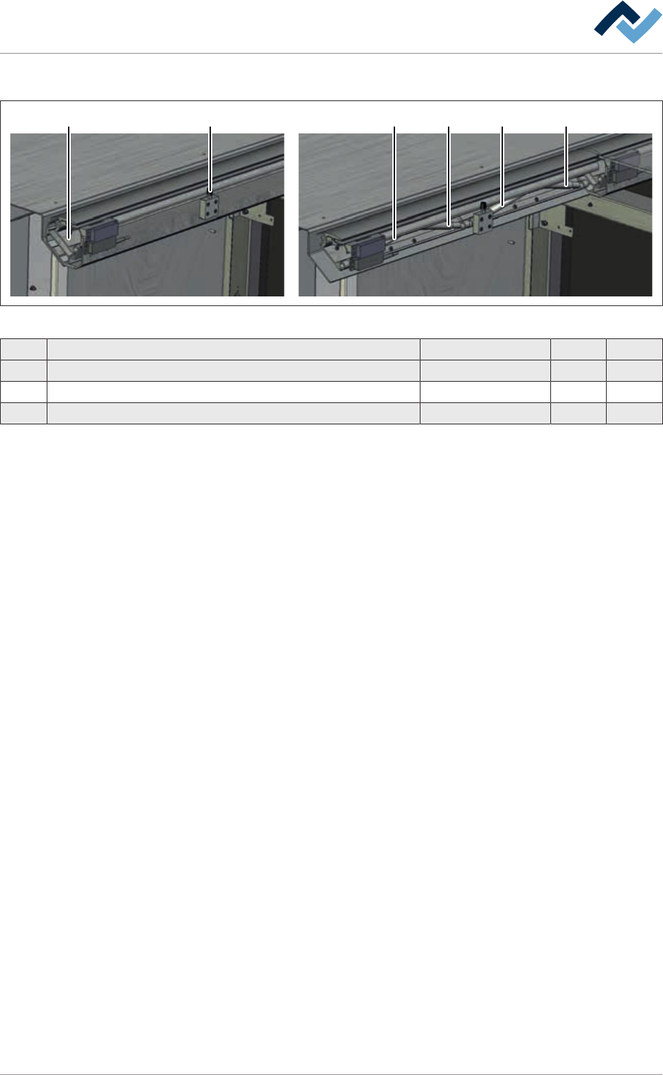
Additional module 900
1 2 3 3 3 3
Fig.148: EM113-15-00a
Pos Designation Item number A B
1 Lever element 86699 x
2 Pressure screw (Neopren) 6GN808-M5-45 x
3 Gas spring (300 N) * 89801 x
*Please note the type designation on the gas spring housing! To mount the gas
spring, Assembly tool for gas spring, item 123716 is required! Always have gas
springs replaced by specialised personnel!
Ersa GmbH Operating Instructions_VF366_en|Rev. 14|30/11/2017 393/551
9|Spare and wear parts
9.3 Spray fluxer and options
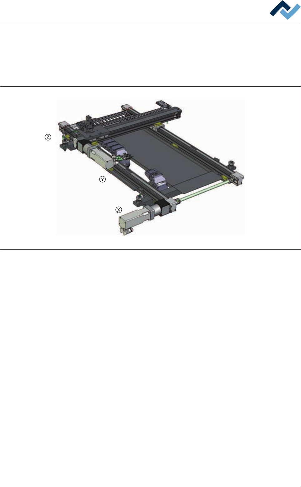
9.3.1 Complete spray fluxer
Overview
Fig.149: EM113-40-00A
Ersa GmbH Operating Instructions_VF366_en|Rev. 14|30/11/2017 394/551
9|Spare and wear parts
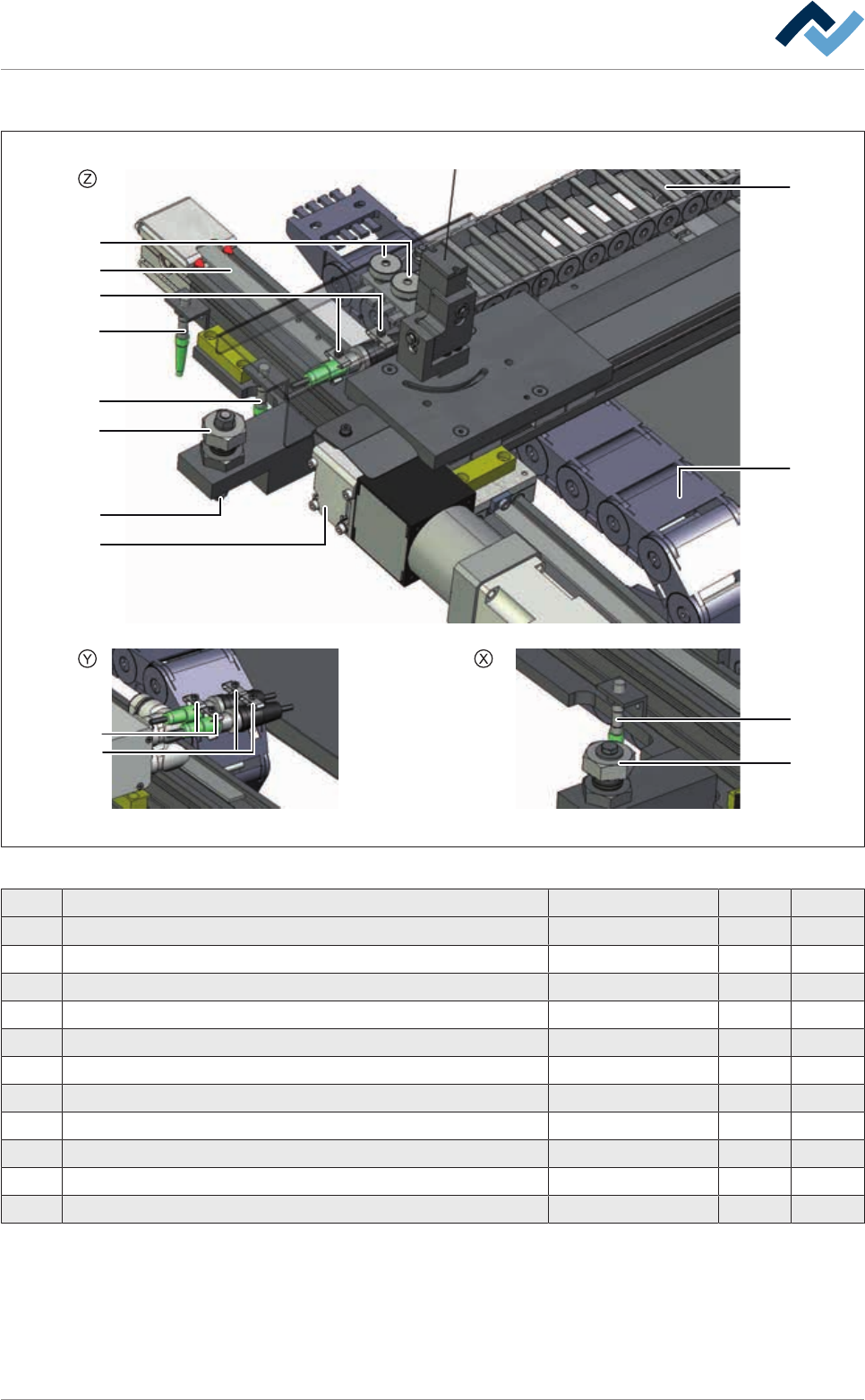
Fluxer complete, view [X], [Y], [Z]
1
2
10
4
5
7
11
6
9
3
1
3
7
8
Fig.150: EM113-40-00a
Pos Description Item number A B
1 Inductive sensor PNP, NC 146183 x
2 Inductive sensor PNP, NO 146185 x
3 Adjusting screw 135733 x
4 Axis of rotation for height adjustment 155309 x
5 Energy chain 155662 x
6 Energy chain X-axis Fluxer 155639 x
7 Spring steel clamp 6FEDKL-G-D6-Z x
8 Hose clip, Euroclip 6SKLS101-12 x
9 Cable bushing 6KATÜ07-10 x
10 Tooth belt 16AT; L = 1845 mm 216459 x
11 Tooth belt 16AT5, 2615 mm 216460 x
Ersa GmbH Operating Instructions_VF366_en|Rev. 14|30/11/2017 395/551