00198608-02_SM_CP20P2_Kunde_EN.pdf - 第21页
3 Component camera, Z axis and component sensor 3.3 Replacing the Z axis cover Service Manual SIPLACE SpeedStar (C&P20 P2) 01/2019 21 Fig.17: Checking the spacing CAUTION! Pay attention to the gap size (2) During …
3 Component camera, Z axis and component sensor
3.3 Replacing the Z axis cover
20 Service Manual SIPLACE SpeedStar (C&P20 P2) 01/2019
Removal
CAUTION
Sensitive lenses
The transmitter and receiver unit lenses on the component sensor are highly sensitive.
► Make sure that you do not damage or contaminate the lens system.
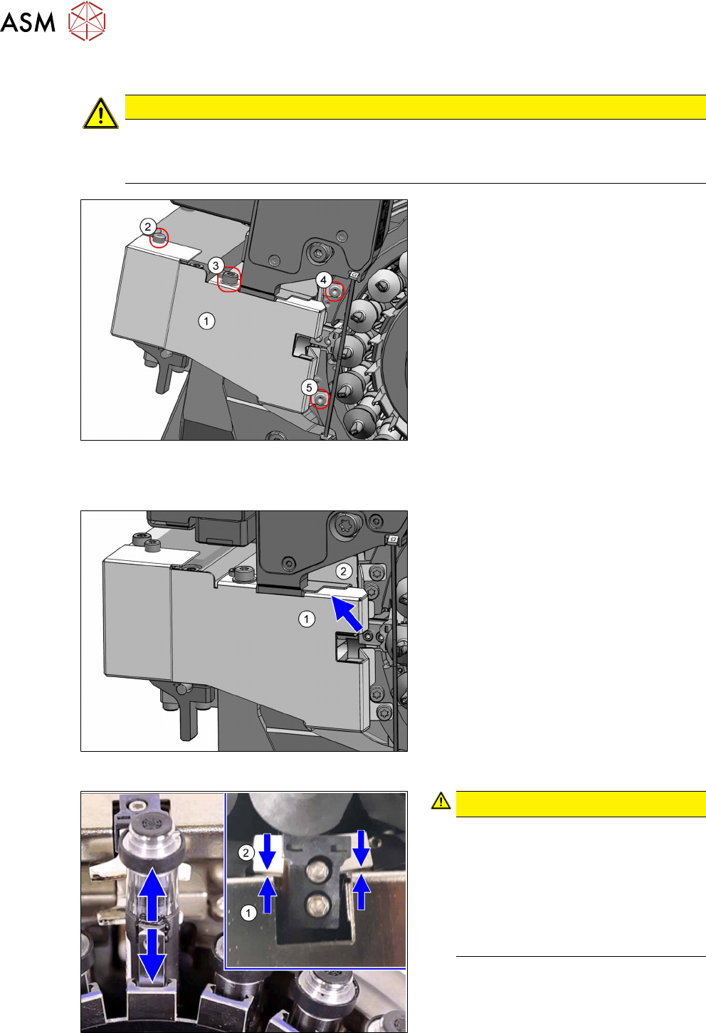
Fig.14: Fastening screws
► Remove the four fastening screws(2)
to(5) and then take the Z axis cover(1)
off.
Installation
Fig.15: Covers
► Place the Z axis cover(1) on the head.
Make sure that the Z axis cover is
under the component protection(2).
Fig.16: Checking the spacing
CAUTION!
Pay attention to the gap size (1)
During the following assembly of the
Z axis cover, pay attention to the gap
size between the Z axis cover (1) and
the jaws(2).
The jaws may not touch the Z axis
cover. If they do, realign the Z axis
cover.
.
3 Component camera, Z axis and component sensor
3.3 Replacing the Z axis cover
Service Manual SIPLACE SpeedStar (C&P20 P2) 01/2019 21
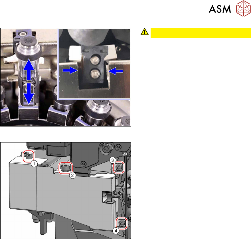
Fig.17: Checking the spacing
CAUTION!
Pay attention to the gap size (2)
During the following assembly of the
Z axis cover, pay attention to the gap
size on the left and right of the Z axis.
If the gap on the left and right is not
the same size, loosen the two screws
on the raceway ((3) and (4), see
below) and realign the Z axis cover.
.
Fig.18: Screws fastening the Z axis cover
► Fasten the Z axis cover with the four
screws. Pay attention to the different
sizes of screws, to the torques and the
gap sizes (see above).
1. Cheese head screws (TX8, 0.7Nm)
2. Cheese head screws (TX10, 1.3Nm)
3. Cheese head screws (TX8, 0.7Nm)
4. Cheese head screws (TX8, 0.7Nm)
3 Component camera, Z axis and component sensor
3.4 Replacing the round magnets
22 Service Manual SIPLACE SpeedStar (C&P20 P2) 01/2019
3.4 Replacing the round magnets
Parts
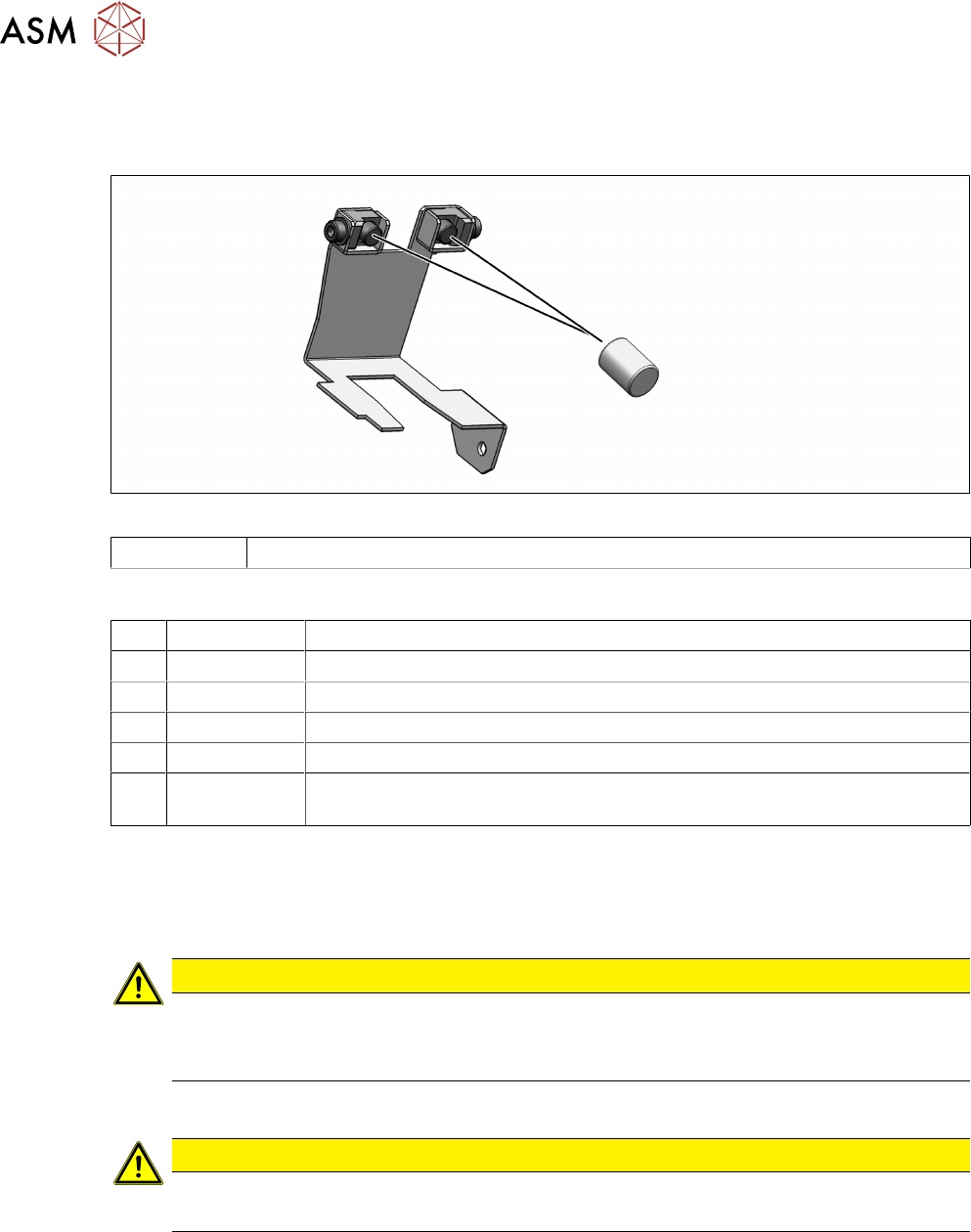
Fig.19: Round magnets on the flexible mounting plate
00349527-xx Round magnet 3x4 neodymium
Equipment and tools
T07 03078400-xx Torque Screwdriver ESD 1.0-5.0 Nm
T45 03078491-xx Magnet removal plate C&P20A
T47 00386253-xx Torque screwdriver ESD 0.4-1.0 Nm
T97 03075862-xx Torque Allen swap blade 1.5 mm TX8
T98 03171857-xx Torque Allen swap blade 1.5 mm TX10
T --- Tools for removing/fitting and calibrating the placement head, if needed
(see also the service manual for your machine)
Preparation
► Remove the head from the machine. For details about removing and fitting the placement
head, refer to the service manual for your machine.
Fit the head on the head mount [03056231‑xx].
CAUTION
Sensitive lenses
The transmitter and receiver unit lenses on the component sensor are highly sensitive.
► Make sure that you do not damage or contaminate the lens system.
Removal
CAUTION
Place the head vertically
► Place the head vertically so that no screws can fall into the Z axis
► Dismantle the Z axis cover.
3.3 "Replacing the Z axis cover" [}19]