00198608-02_SM_CP20P2_Kunde_EN.pdf - 第62页
8 Return unit 8.1 Replacing the return unit, cylinder, holder and driver lever 62 Service Manual SIPLACE SpeedStar (C&P20 P2) 01/2019 Preparation ► Remove the head from the machine. For details about removing and fit…
8 Return unit
8.1 Replacing the return unit, cylinder, holder and driver lever
Service Manual SIPLACE SpeedStar (C&P20 P2) 01/2019 61
8 Return unit
8.1 Replacing the return unit, cylinder, holder and driver
lever
Parts
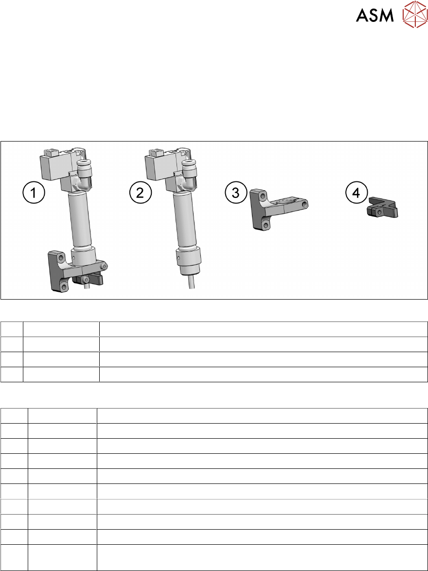
Fig.81: Return unit
1 03128518-xx Return unit assembly SIPLACE C&P20 P2
2 03007696-xx Return cylinder SIPLACE C&P20
3 03128516-xx Return cylinder holder SIPLACE C&P20 P2
4 03128517-xx Driver lever for return cylinder SIPLACE C&P20 P2
Equipment and tools
T07 03078400-xx Torque Screwdriver ESD 1.0-5.0 Nm
T19 00318673-xx Wire cutter electronic size 110
T47 00386253-xx Torque screwdriver ESD 0.4-1.0 Nm
T77 00386136-xx Torque interchangeable blades 2 mm, hexagonal
T78 03090019-xx Torque interchangeable blades 2.5 mm, hexagonal
T97 03075862-xx Torque Allen swap blade 1.5 mm TX8
T98 03171857-xx Torque Allen swap blade 1.5 mm TX10
T 00094020-xx Feeler gauge size 20 - 0.05 - 1.0 mm
C08 00308458-xx Cable ties B=2.5mm, L=102mm Panduit
T --- Tools for removing/fitting and calibrating the placement head, if needed
(see also the service manual for your machine)
8 Return unit
8.1 Replacing the return unit, cylinder, holder and driver lever
62 Service Manual SIPLACE SpeedStar (C&P20 P2) 01/2019
Preparation
► Remove the head from the machine. For details about removing and fitting the placement
head, refer to the service manual for your machine.
Fit the head on the head mount [03056231‑xx].
► Make sure that the component sensor protective cap is fitted.
1.1.3 "Safety instructions for the component sensor" [}6]
Removing the return cylinder
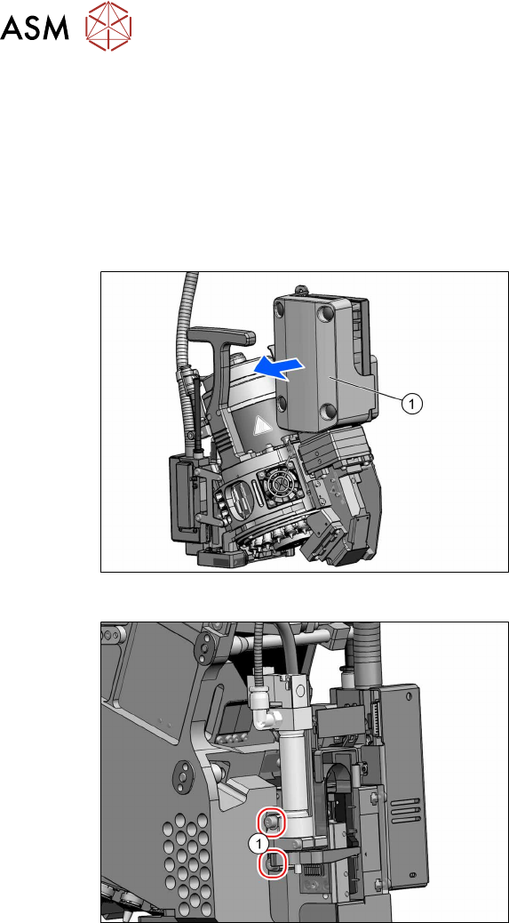
Fig.82: Pulling the cover off
► Pull the cover(1) off the intermediate
distributor.
The cover is fixed by four press studs
on the stay bolts.
Fig.83: Dismantling the return cylinder
► Remove the two screws(1) (TX10)
fastening the return unit and then care-
fully pull the return unit slightly out of
the head.
8 Return unit
8.1 Replacing the return unit, cylinder, holder and driver lever
Service Manual SIPLACE SpeedStar (C&P20 P2) 01/2019 63
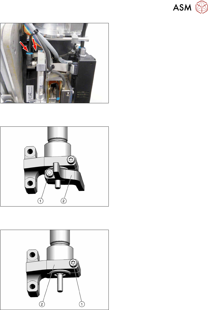
Fig.84: Electrical and pneumatic connections
► Unplug all electrical and pneumatic
connections. If necessary, mark their
positions to make clear assignment
easier later on.
► If you are replacing the whole return
unit assembly, continue with the install-
ation of the return unit.
Removing the driver lever
Fig.85: Driver lever - fastening screw
► Loosen the screw(1) (Allen2) fasten-
ing the driver lever(2).
► Pull the driver lever down and off.
► If you are only replacing the driver
lever, continue with installation of the
driver lever.
Removing the return cylinder holder
Fig.86: Driver lever - fastening screw
► Loosen the screw(1) (TX8) fastening
the return cylinder holder(2).
► Pull the return cylinder holder down
and off.