RF103-5继电器数据表.pdf
RF100 RF103 P age 19 SPECIFICA TIONS ARE SUBJECT T O CHANGE WITHOUT NO TICE ©2003 TELED YNE RELA YS www .teledynerelays.com RF100 RF103/1203/Q1 RF & MICROW A VE SERIES RF100 RF103 HIGH REPEA T ABILITY BR O ADB AND CE…
RF100 RF103 Page 19 SPECIFICATIONS ARE SUBJECT TO CHANGE WITHOUT NOTICE ©2003 TELEDYNE RELAYS
www.teledynerelays.com RF100 RF103/1203/Q1
RF & MICROWAVE
SERIES
RF100
RF103
HIGH REPEATABILITY
BROADBAND
CENTIGRID
®
RELAYS
DPDT
SERIES
DESIGNATION
RELAY TYPE
RF100 Repeatable, RF, Centigrid
®
relay
RF103 Sensitive, repeatable, RF, Centigrid
®
relay
PERFORMANCE FEATURES
The ultraminiature RF100 and RF103 relays are designed to provide improved
RF signal repeatability over the frequency range. These relays are highly
suitable for use in attenuator and other RF circuits, the RF100 and RF103
feature:
• High repeatability.
• Broader bandwidth.
• Metal enclosure for EMI shielding.
• Ground pin option to improve case grounding.
• High isolation between control and signal paths.
• Highly resistant to ESD.
CONSTRUCTION FEATURES
The following unique construction features and manufacturing techniques
provide excellent resistance to environmental extremes and overall high
reliability.
• Uni-frame motor design provides high magnetic efficiency and mechanical
rigidity.
• Minimum mass components and welded construction provide maximum
resistance to shock and vibration.
• Advanced cleaning techniques provide maximum assurance of internal
cleanliness.
• Gold-plated precious metal alloy contacts ensure reliable switching.
• Hermetically sealed.
• Solderable leads.
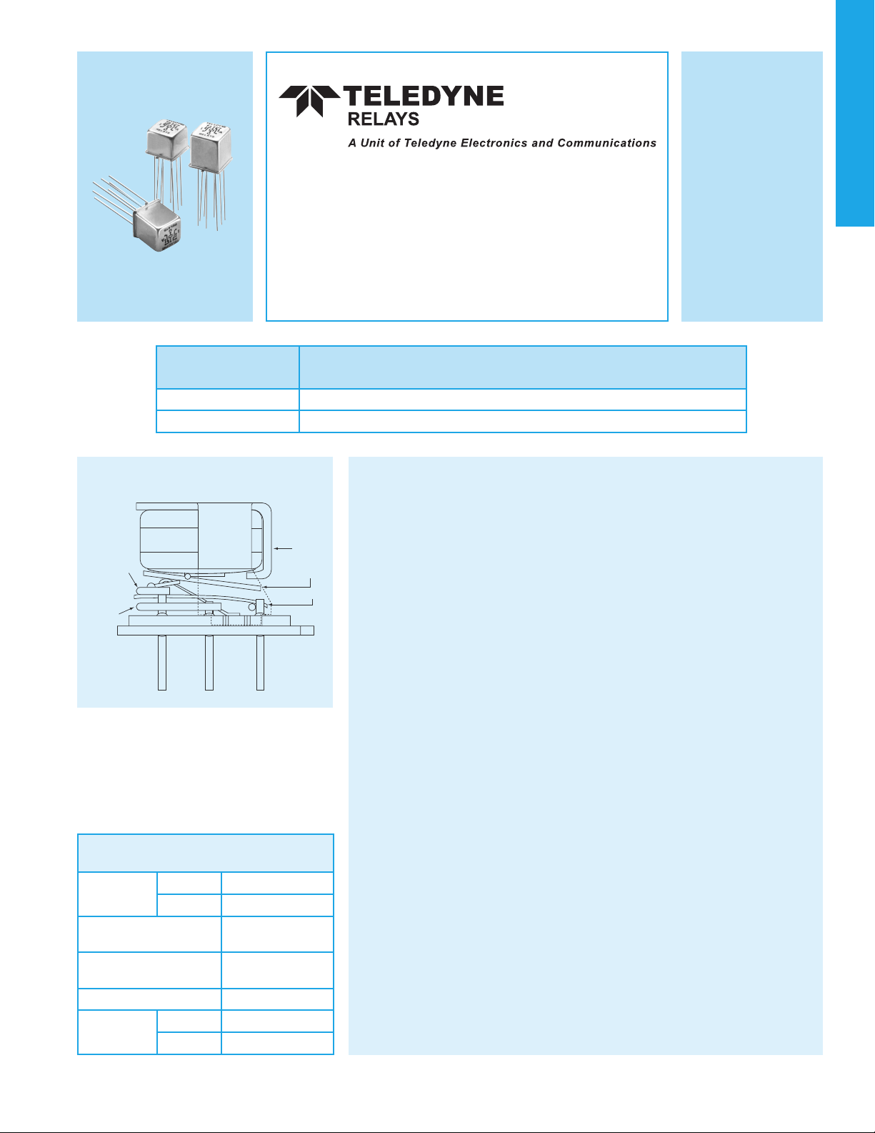
INTERNAL CONSTRUCTION
UNI-FRAME
UPPER
STATIONARY
CONTACT
LOWER
STATIONARY
CONTACT
ARMATURE
MOVING CONTACT
ENVIRONMENTAL AND
PHYSICAL SPECIFICATIONS
Temperature
(Ambient)
Storage –65°C to +125°C
Operating –55°C to +85°C
Vibration
(General Note 1)
10 g’s to 500 Hz
Shock
(General Note 1)
30 g’s,
6 msec, half-sine
Enclosure Hermetically sealed
Weight
RF100 0.09 oz. (2.55g) max.
RF103 0.16 oz. (4.5g) max.
©2003 TELEDYNE RELAYS SPECIFICATIONS ARE SUBJECT TO CHANGE WITHOUT NOTICE RF100 RF103 Page 20
www.teledynerelays.com RF100 RF103/1203/Q1
RF & MICROWAVE
RF NOTES
1. Test conditions: a. Fixture: .031" copper clad, reinforced PTFE, RT/duroid
®
6002 with SMA connectors. (RT/duroid
®
is a
registered trademark of Rogers Corporation.)
b. Room ambient temperature.
c. Terminals not tested were terminated with 50-ohm load.
d. Contact signal level: –10 dBm.
e. No. of test samples: 2.
2. Data presented herein represents typical characteristics and is not intended for use as specification limits.
3. Data is per pole, except for pole-to-pole data.
4. Data is the average from readings taken on all open contacts.
5. Data is the average from readings taken on poles with coil energized and de-energized.
6. Data is the average from readings taken on all closed contacts.
7. Test fixture effect de-embedded from frequency and time response data.
SERIES RF100 AND RF103
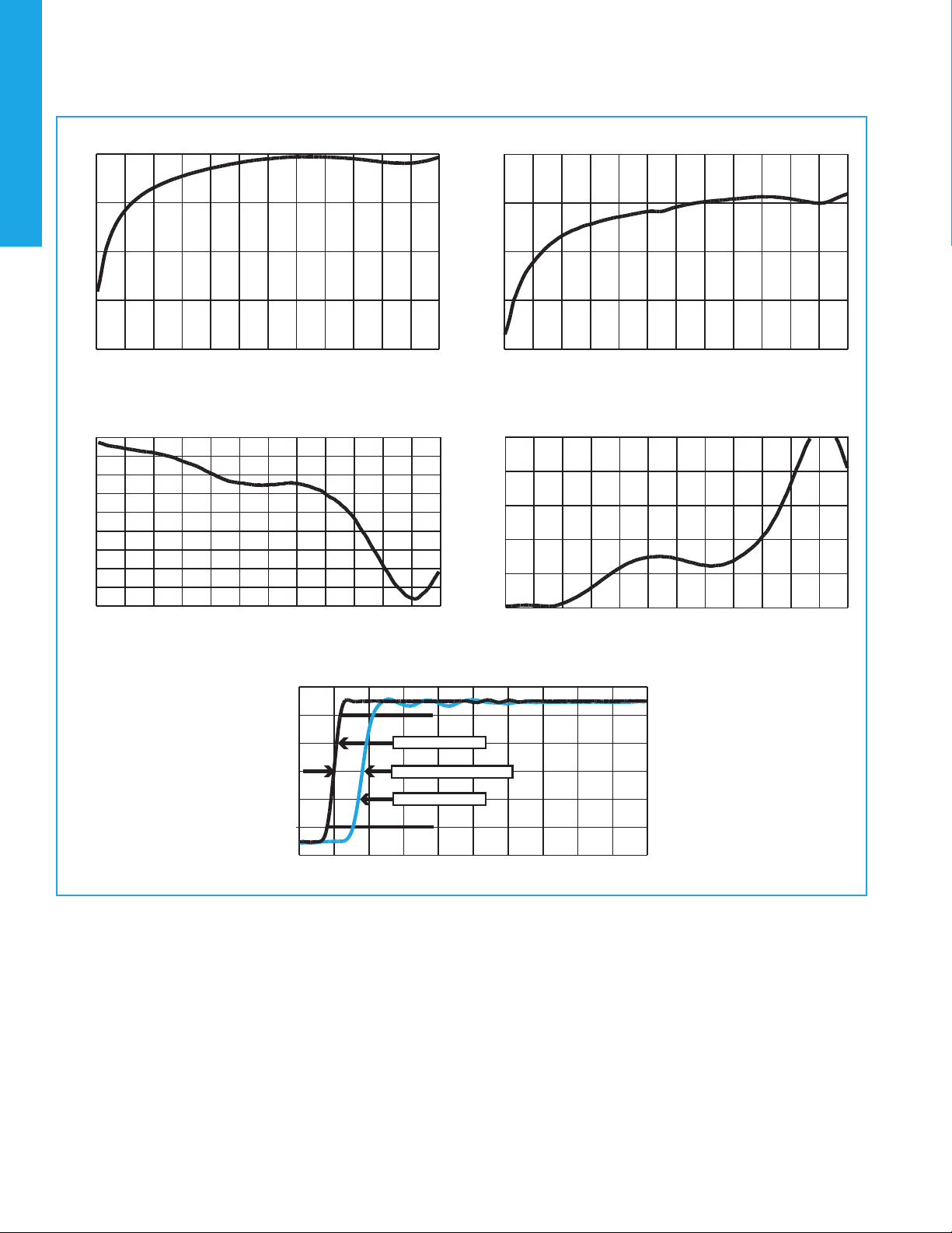
TYPICAL RF CHARACTERISTICS (See RF Notes)
Isolation Across Contacts (RF Note 4)
-60
-50
-40
-30
-20
0 500 1000 1500 2000 2500 3000 3500 4000 4500 5000 5500 6000
Frequency (MHz)
Isolation (dB)
Isolation Pole to Pole (RF Note 5)
-60
-50
-40
-30
-20
0 500 1000 1500 2000 2500 3000 3500 4000 4500 5000 5500 6000
Frequency (MHz)
Isolation (dB)
Insertion Loss (RF Note 6)
-1.8
-1.6
-1.4
-1.2
-1
-0.8
-0.6
-0.4
-0.2
0
0 500 1000 1500 2000 2500 3000 3500 4000 4500 5000 5500 6000
Frequency (MHz)
Insertion Loss (dB)
VSWR (RF Note 6)
1.00
1.40
1.80
2.20
2.60
3.00
0 500 1000 1500 2000 2500 3000 3500 4000 4500 5000 5500 6000
Frequency (MHz)
VSWR
RF100 Time Response (RF Note 6)
-0.1
0.1
0.3
0.5
0.7
0.9
1.1
-100 0 100 200 300 400 500 600 700 800 900
Time (ps)
Volt
10%
90%
37ps reference
58.1ps pulse rise time
81.1ps propagation delay time
RF100 RF103 Page 21 SPECIFICATIONS ARE SUBJECT TO CHANGE WITHOUT NOTICE ©2003 TELEDYNE RELAYS
www.teledynerelays.com RF100 RF103/1203/Q1
RF & MICROWAVE
RF INSERTION LOSS REPEATABILITY NOTES
1. Test conditions: a. Fixture: .031" copper clad, reinforced PTFE, RT/duroid
®
6002 with SMA connectors. (RT/duroid
®
is a
registered trademark of Rogers Corporation.)
b. Relay header is in contact with, but not soldered to, ground plane or connected to ground via ground pin.
c. Test performed at room ambient temperature.
d. Contact signal level: 20 dBm.
2. Data presented herein represents typical characteristics and is not intended for use as specification limits.
3. Insertion loss repeatability measured over frequency range from .3 MHz to 4 GHz.
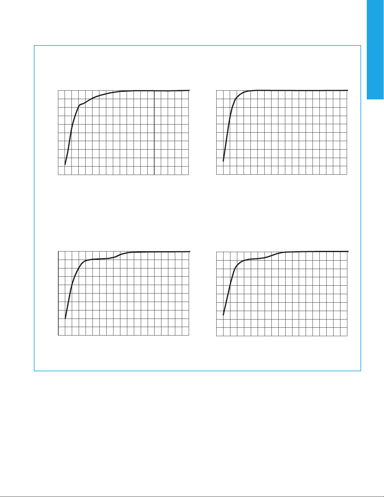
TYPICAL RF INSERTION LOSS REPEATABILITY CHARACTERISTICS (NOTES 1 AND 2)
SERIES RF100 AND RF103
100
90
80
70
60
50
40
30
20
10
0
0.02 0.04 0.06 0.08 0.10 0.12 0.14 0.16 0.18 0.20
Repeatability (dB) Repeatability (dB)
Repeatability (dB) Repeatability (dB)
REPEATABILITY CHARACTERISTICS RF100 RELAYS
100
90
80
70
60
50
40
30
20
10
0
100
90
80
70
60
50
40
30
20
10
0
100
90
80
70
60
50
40
30
20
10
0
REPEATABILITY CHARACTERISTICS RF103 RELAYS
Normally Open
Normally Open
Normally Closed
Normally Closed
% Total Number Recorded Test Cycles% Total Number Recorded Test Cycles
% Total Number Recorded Test Cycles% Total Number Recorded Test Cycles
0.02 0.04 0.06 0.08 0.10 0.12 0.14 0.16 0.18 0.20
0.02 0.04 0.06 0.08 0.10 0.12 0.14 0.16 0.18 0.20 0.02 0.04 0.06 0.08 0.10 0.12 0.14 0.16 0.18 0.20