RF103-5继电器数据表.pdf - 第3页
RF100 RF103 P age 21 SPECIFICA TIONS ARE SUBJECT TO CHANGE WITHOUT NOTICE ©2003 TELED YNE RELA YS www .teledynerelays.com RF100 RF103/1203/Q1 RF & MICROW A VE RF INSERTION LOSS REPEA T ABILITY NO TES 1. T est conditi…
©2003 TELEDYNE RELAYS SPECIFICATIONS ARE SUBJECT TO CHANGE WITHOUT NOTICE RF100 RF103 Page 20
www.teledynerelays.com RF100 RF103/1203/Q1
RF & MICROWAVE
RF NOTES
1. Test conditions: a. Fixture: .031" copper clad, reinforced PTFE, RT/duroid
®
6002 with SMA connectors. (RT/duroid
®
is a
registered trademark of Rogers Corporation.)
b. Room ambient temperature.
c. Terminals not tested were terminated with 50-ohm load.
d. Contact signal level: –10 dBm.
e. No. of test samples: 2.
2. Data presented herein represents typical characteristics and is not intended for use as specification limits.
3. Data is per pole, except for pole-to-pole data.
4. Data is the average from readings taken on all open contacts.
5. Data is the average from readings taken on poles with coil energized and de-energized.
6. Data is the average from readings taken on all closed contacts.
7. Test fixture effect de-embedded from frequency and time response data.
SERIES RF100 AND RF103
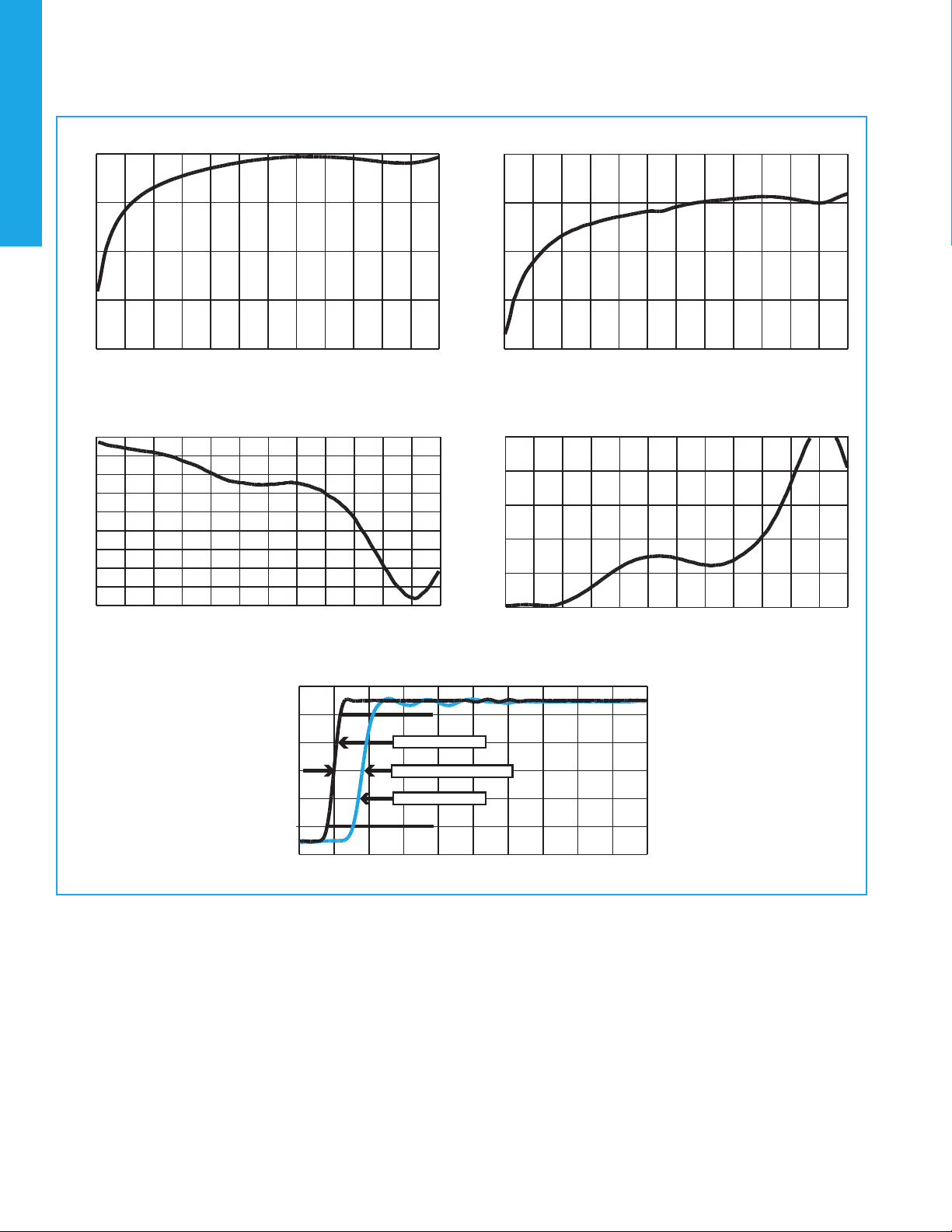
TYPICAL RF CHARACTERISTICS (See RF Notes)
Isolation Across Contacts (RF Note 4)
-60
-50
-40
-30
-20
0 500 1000 1500 2000 2500 3000 3500 4000 4500 5000 5500 6000
Frequency (MHz)
Isolation (dB)
Isolation Pole to Pole (RF Note 5)
-60
-50
-40
-30
-20
0 500 1000 1500 2000 2500 3000 3500 4000 4500 5000 5500 6000
Frequency (MHz)
Isolation (dB)
Insertion Loss (RF Note 6)
-1.8
-1.6
-1.4
-1.2
-1
-0.8
-0.6
-0.4
-0.2
0
0 500 1000 1500 2000 2500 3000 3500 4000 4500 5000 5500 6000
Frequency (MHz)
Insertion Loss (dB)
VSWR (RF Note 6)
1.00
1.40
1.80
2.20
2.60
3.00
0 500 1000 1500 2000 2500 3000 3500 4000 4500 5000 5500 6000
Frequency (MHz)
VSWR
RF100 Time Response (RF Note 6)
-0.1
0.1
0.3
0.5
0.7
0.9
1.1
-100 0 100 200 300 400 500 600 700 800 900
Time (ps)
Volt
10%
90%
37ps reference
58.1ps pulse rise time
81.1ps propagation delay time
RF100 RF103 Page 21 SPECIFICATIONS ARE SUBJECT TO CHANGE WITHOUT NOTICE ©2003 TELEDYNE RELAYS
www.teledynerelays.com RF100 RF103/1203/Q1
RF & MICROWAVE
RF INSERTION LOSS REPEATABILITY NOTES
1. Test conditions: a. Fixture: .031" copper clad, reinforced PTFE, RT/duroid
®
6002 with SMA connectors. (RT/duroid
®
is a
registered trademark of Rogers Corporation.)
b. Relay header is in contact with, but not soldered to, ground plane or connected to ground via ground pin.
c. Test performed at room ambient temperature.
d. Contact signal level: 20 dBm.
2. Data presented herein represents typical characteristics and is not intended for use as specification limits.
3. Insertion loss repeatability measured over frequency range from .3 MHz to 4 GHz.
TYPICAL RF INSERTION LOSS REPEATABILITY CHARACTERISTICS (NOTES 1 AND 2)
SERIES RF100 AND RF103
100
90
80
70
60
50
40
30
20
10
0
0.02 0.04 0.06 0.08 0.10 0.12 0.14 0.16 0.18 0.20
Repeatability (dB) Repeatability (dB)
Repeatability (dB) Repeatability (dB)
REPEATABILITY CHARACTERISTICS RF100 RELAYS
100
90
80
70
60
50
40
30
20
10
0
100
90
80
70
60
50
40
30
20
10
0
100
90
80
70
60
50
40
30
20
10
0
REPEATABILITY CHARACTERISTICS RF103 RELAYS
Normally Open
Normally Open
Normally Closed
Normally Closed
% Total Number Recorded Test Cycles% Total Number Recorded Test Cycles
% Total Number Recorded Test Cycles% Total Number Recorded Test Cycles
0.02 0.04 0.06 0.08 0.10 0.12 0.14 0.16 0.18 0.20
0.02 0.04 0.06 0.08 0.10 0.12 0.14 0.16 0.18 0.20 0.02 0.04 0.06 0.08 0.10 0.12 0.14 0.16 0.18 0.20
©2003 TELEDYNE RELAYS SPECIFICATIONS ARE SUBJECT TO CHANGE WITHOUT NOTICE RF100 RF103 Page 22
www.teledynerelays.com RF100 RF103/1203/Q1
RF & MICROWAVE
SERIES RF100 AND RF103
GENERAL ELECTRICAL SPECIFICATIONS (@25°C)
DETAILED ELECTRICAL SPECIFICATIONS (@25°C)
GENERAL NOTES
1. Relays will exhibit no contact chatter in excess of 10 µsec or transfer in excess of 1 µsec.
Contact arrangement DPDT
Rated duty Continuous
Contact resistance .100 ohm max. initial (measured 1/8" from the header)
Contact load rating Low level: 10 to 50 µA, 10 to 50 mV
Contact life rating 10,000,000 cycles typical at low level
Coil operating power
RF100: 369–500 mW typical @ nominal rated voltage
RF103: 180–250 mW typical @ nominal rated voltage
Operate time
RF100 4.0 ms. max.
RF103 6.0 ms. max.
Release time
RF100 3.0 ms. max.
RF103 3.0 ms. max.
Intercontact capacitance 0.4 pF typical
Insulation resistance
1,000 MΩ min. (between mutually isolated terminals)
Dielectric strength 350 VRMS / 60 Hz @ atmospheric pressure
BASE PART NUMBERS
RF100-5
RF103-5
RF100-12
RF103-12
Coil voltage, nominal, VDC 5.0 12.0
Coil resistance, ohms ± 20%
RF100 50 390
RF103 100 800
Pick-up voltage max, VDC 3.6 9.0
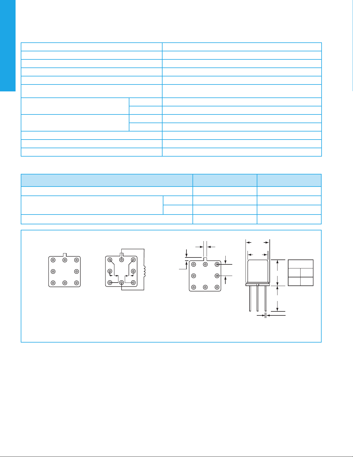
OUTLINE DIMENSIONS
• TERMINAL NUMBERING AND SCHEMATIC ARE AS VIEWED FROM THE TERMINALS.
• DIMENSIONS ARE IN INCHES (MILLIMETERS).
• SCHEMATIC AND EXTERNAL DIMENSIONS SHOWN WITHOUT GROUND PINS.
• TO ORDER THE CASE GROUND OPTION, AFTER THE SERIES DESIGNATOR, ADD “Y” TO
THE PART NUMBER FOR TAB POSITION OR “Z” TO THE PART NUMBER FOR CENTER
POSITION.
EXAMPLE: RF103Y-COIL VOLTAGE
EXTERNAL DIMENSIONS
TERMINAL NUMBERING
SCHEMATIC
.031 (.79)
REF.
.035 (.89)
REF.
1
2
3
4
5
6
7
8
H DIMENSION
RF100
RF103
.290
(7.37)
.395
(10.03)
MAX.
.017
+.002
-.001
()
.43
+.05
-.03
.335
(8.51)
SQ. MAX.
.375
(9.53)
SQ. MAX.
H
.75 (19.05) MIN.
0.100 0.010
(2.54 0.25)