88192278-01-19 Installation Master.pdf - 第103页
PRINTER PREPARATION GENERAL Chapter Issue 15, May 20 Installation Manual 4.1 CHAPTER 4 PR INTER PREP ARA TION GENERAL Prior to printer power up it is essential to follow the preparation instructions in this section thus …

SERVICES REQUIRED
CENTRE OF GRAVITY AND SEISMIC ANCHORAGE
3.12 Installation Manual Chapter Issue 16, Nov 19

PRINTER PREPARATION
GENERAL
Chapter Issue 15, May 20 Installation Manual 4.1
CHAPTER 4 PRINTER PREPARATION
GENERAL Prior to printer power up it is essential to follow the preparation instructions in
this section thus ensuring correct operation of the printer and prevent any
possible damage occurring to the printer or personnel.
NOTE
Do not remove the red transit brackets, tie wraps or screws attached to the
printer until the printer has been moved to its designated position.
Using the Pack List, ensure that all items are supplied.
Visually inspect all printer components and equipment for completeness,
condition and damage. If any components or equipment are incomplete,
damaged or in poor condition, make a note of this on the Outstanding Issues
page found in the Installation Documentation chapter of this manual.
Transportation
WARNING
MACHINE LIFTING. TO PREVENT SERIOUS INJURY TO PERSONNEL, DURING
LIFTING AND TRANSPORTATION OPERATIONS, ENSURE THE MACHINE IS
LIFTED AND TRANSPORTED IN ACCORDANCE WITH INSTRUCTIONS DETAILED
IN THIS SECTION.
NOTE
Damage to the printer will occur if the printer is lifted:
• Using lifting strops
OR...
• From the sides
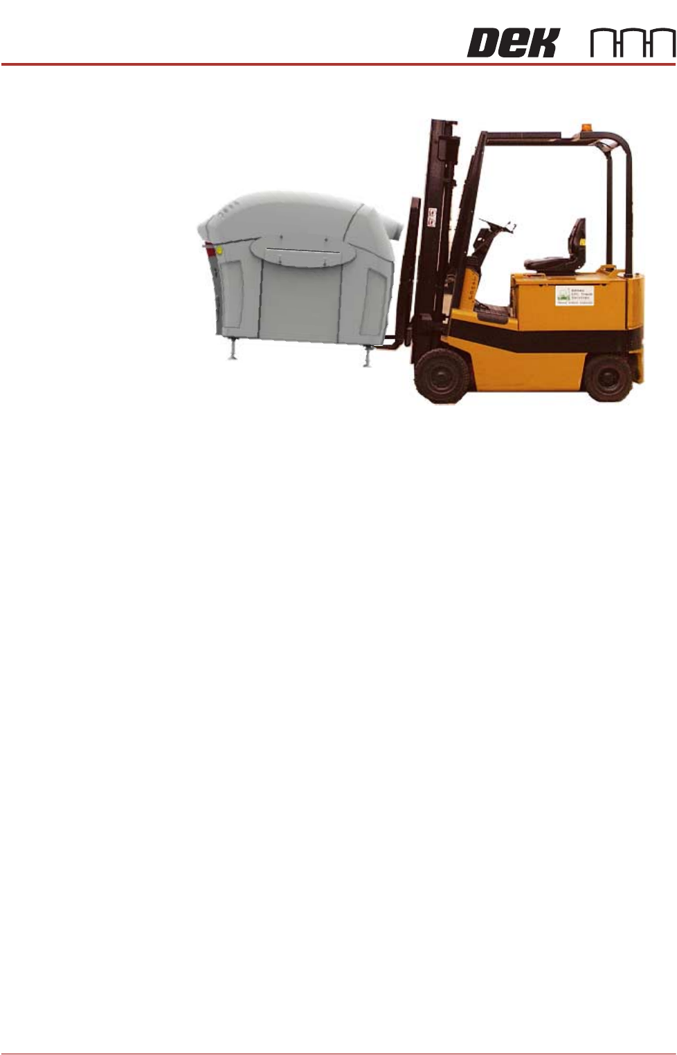
ASM recommends that the printer is lifted from the rear at all times however,
the printer may be lifted from the front if the printer is to be moved a short
distance or moved into line.
The printer may be lifted using a forklift truck or similar printer that meets the
following criteria:
• Minimum fork length of 1372mm (54 inches)
• Fork span >686mm (27 inches) and <914mm (36 inches)
• Fork Height (thickness) <50mm (2 inches)
• Lifting capability of 2000kg
PRINTER PREPARATION
GENERAL
4.2 Installation Manual Chapter Issue 15, May 20
1. Locate the forks under the printer base.
2. Raise the forks, separating the printer from the base of the transportation
box.
3. For printers with the anti-vibration mounting option, four leg spacers and one
standard foot is supplied. Ensure the correct number of leg spacers are fitted
to the four corners of the printer when it is located into the production line.30
4. Move the printer to its designated position.