88192278-01-19 Installation Master.pdf - 第123页
PRINTER PREPARATION PRINTER HEIGHT AND LEVELLING Chapter Issue 15, May 20 Installation Manual 4.21 to back. 17. C hange the orientation of the Level and adjust the front centre moun ting foot (6) to level the printer in …
PRINTER PREPARATION
PRINTER HEIGHT AND LEVELLING
4.20 Installation Manual Chapter Issue 15, May 20
8. Lower the printer onto the floor plate, ensuring foot (3) and foot (4) are
positioned correctly on the plate and clear of the location and V- blocks.
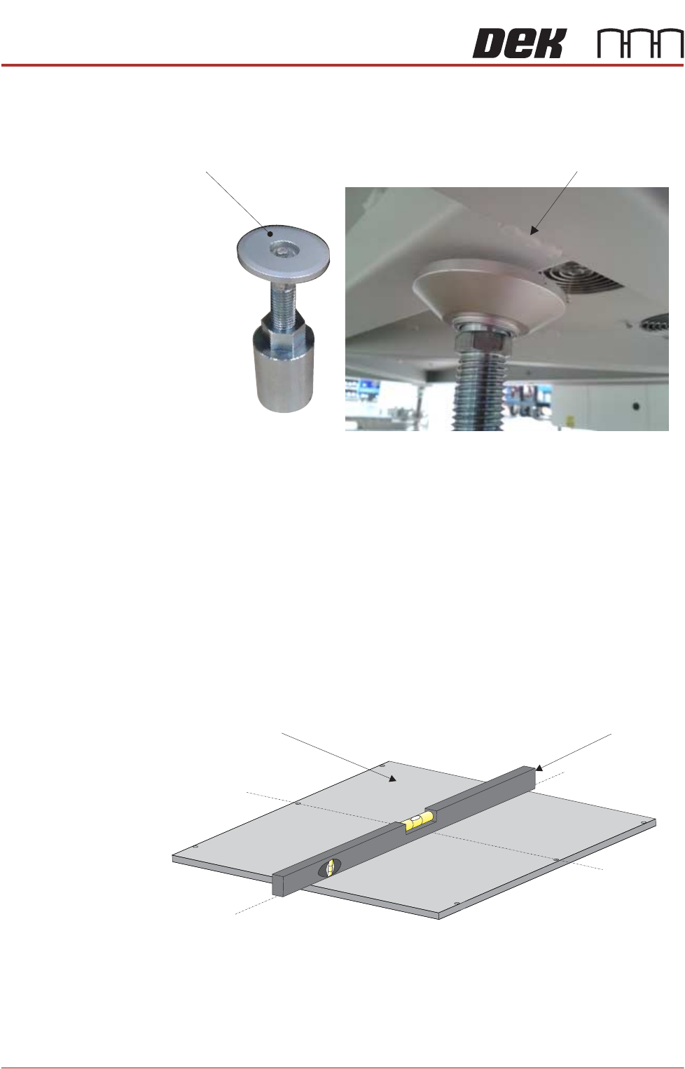
9. Place foot (6) under the front of the printer in the centre.
10. Check the orientation of foot (6) as shown above.
NOTE
Avoid the seam weld to ensure the printer is properly supported.
11. Raise the front centre levelling foot (6) to make contact with the printer.
12. Raise the front left foot (1) and front right foot (2) so they are not in contact
with the floor and the printer is supported on the centre mounting foot (6).
13. Apply pneumatic power to the printer to set the rails to the correct height for
printer levelling.
14. Place an engineering level on top of the manual tooling plate along the front
row of screws running from left to right.
15. Adjust the rear mounting foot (3) and foot (4) to level the printer in the X
direction.
16. Move the engineering level along the centre row of screws running from front
Seam WeldLevelling Foot (6)
Front below FrameView Machine
Engineering LevelManual Tooling Plate
Isometric View on Manual Tooling Plate
Front
Centre Line
(Y direction)
Centre Line
(X direction)
PRINTER PREPARATION
PRINTER HEIGHT AND LEVELLING
Chapter Issue 15, May 20 Installation Manual 4.21
to back.
17. Change the orientation of the Level and adjust the front centre mounting foot
(6) to level the printer in the Y direction.
18. Repeat Steps 16 to 18 until the printer is level in both directions.
19. Carefully lower the front left mounting foot (1) so that it is in contact with the
floor.
20. Recheck the printer level has not been disturbed.
21. Carefully lower the front right mounting foot (2) so that it is in contact with
the floor.
22. Recheck the printer level has not been disturbed.
23. Lower the front centre mounting foot (6) so it is not in contact with the printer.
24. Remove the front centre mounting foot (6) and store in a safe place.
25. Tighten mounting feet locknuts.
26. Recheck the printer is level.
27. Recheck the printer height has not been disturbed.
28. Remove the engineering level from the printer.
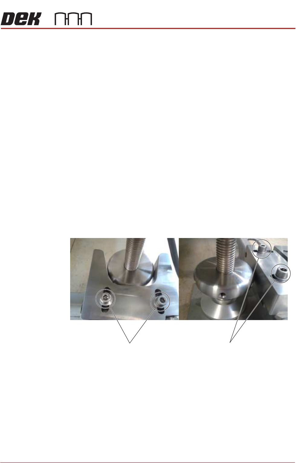
29. Position the V-block so contact is made with the locating collar on foot (3).
30. Position the location block so contact is made with the locating collar on foot
(4).
31. Fully tighten the fixing screws securing both location blocks.
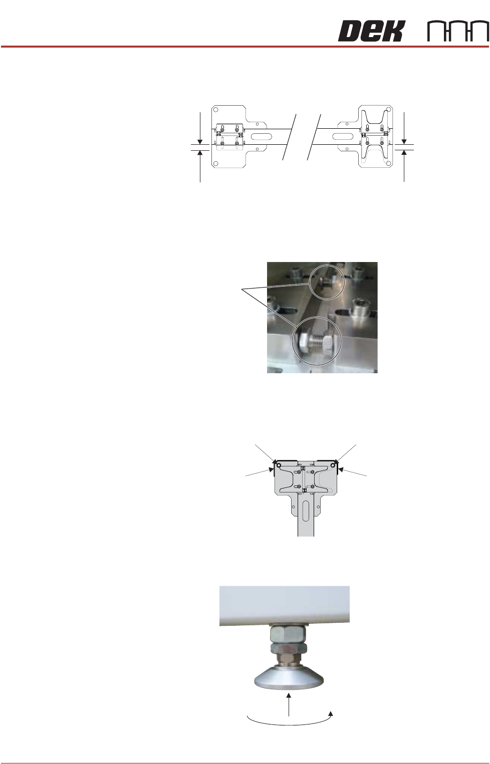
32. Position the locator blocks for printer B to achieve maximum adjustment,
V-Block
Fixing Screws
Location-Block
Fixing Screws
PRINTER PREPARATION
PRINTER HEIGHT AND LEVELLING
4.22 Installation Manual Chapter Issue 15, May 20
and ensure parallel to the locator blocks for printer A.
33. Fully tighten the fixing screws for the printer B location blocks.
34. Rotate the stopper bolts by hand until they make contact with the opposing
block, and then secure them using the locknuts.
35. Using a permanent marker pen, draw around the outline of each corner and
the corner holes of the floor plate to provide 8 reference marks, this will
highlight any movement during installation.
Levelling and
Positioning (Printer
B)
1. Raise the rear centre mounting foot (5) to the highest position to avoid
contact with the floor plate.
2. Move printer B into position so that it is roughly aligned to its downline
ADJUSTMENT
LOCATION BLOCK
ADJUSTMENT
V-BLOCK
Stopper Bolts
Reference MarkReference Mark
Reference Mark Reference Mark