YRM20_Mainte_E.pdf - 第107页
4. 6-month maintenance 3-40 Chapter 3 Periodic maintenance items 4.1.4 Side view camera [RM head] T he RM head unit is equipped the lighting diffuser plate of side view camera and the mirror . T he lighting or the apertu…
4. 6-month maintenance
3-39
Chapter 3 Periodic maintenance items
4.1.3 Scan camera [HM head]
The lighting diffuser plate of scan camera and prism are mounted at the aperture located at left end of
camera. The diffuser plate and prism may be soiled with dust and dirt during long term using. The periodical
cleaning is recommended.
c
CAUTION
Do not apply strong force or shock to the camera unit during cleaning. The glass parts installed inside of camera may be
damaged.
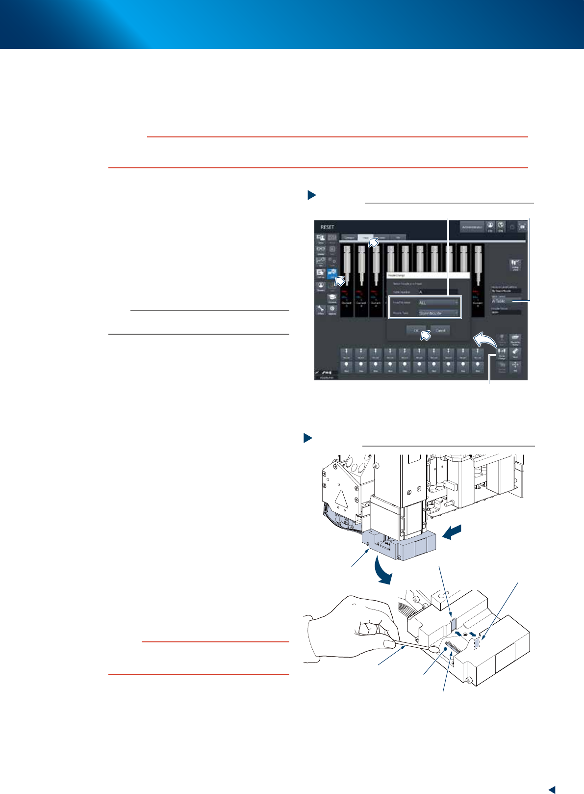
1
Store all the nozzles.
1. Open [Unit] - [Head] screen.
2. Select any head unit from "Table Select".
3. Press the [Nozzle Change] button.
4. Select "ALL" for "Head Number" and select
"Store Nozzle" for "Nozzle Type" on the
"Nozzle Change" screen.
5. Press the [OK] button to return all nozzles to
the nozzle station.
n
NOTE
When the nozzle station is not installed, press the
emergency stop button and remove nozzles by hand.
e
2
Move the head unit.
1. Press the emergency stop button and detach
the feeder exchange carriage.
2. Open the machine safety cover and move
the head unit by hand to the convenient
position to work.
3
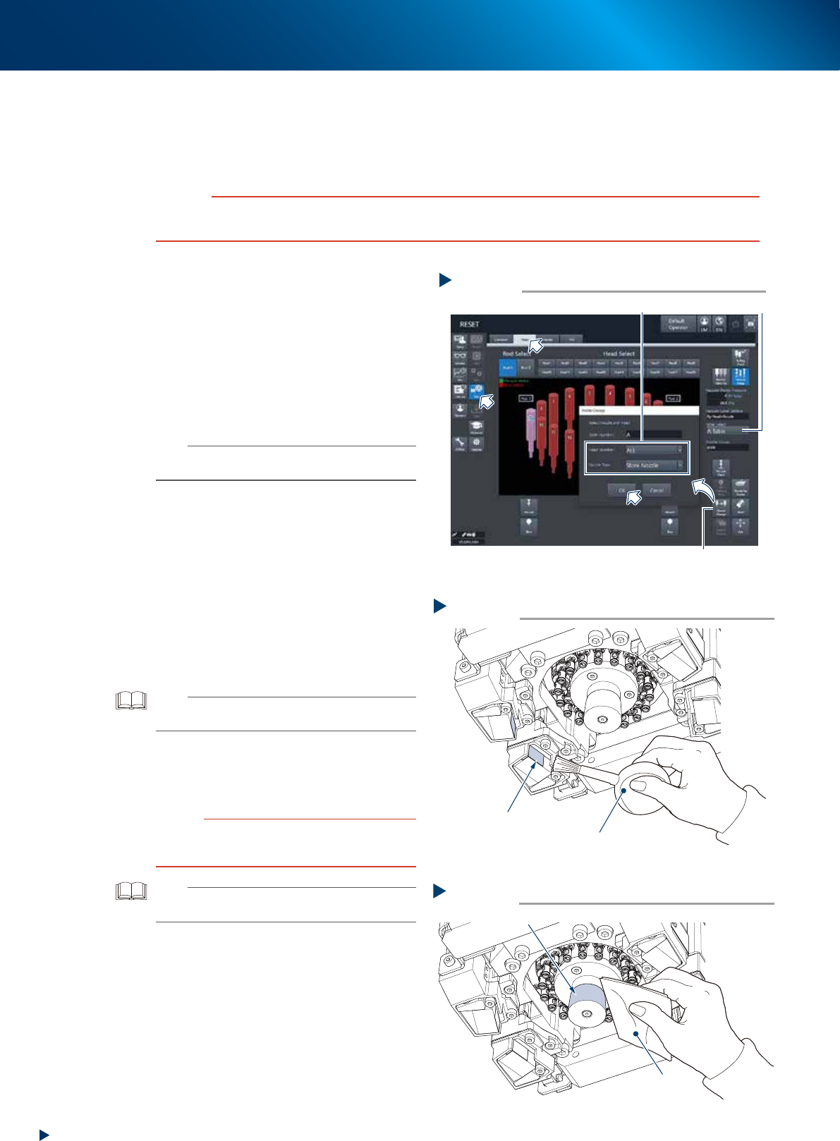
Move the scan camera.
1. Confirm that all the heads stay at their
topmost position. When they interfere the
scan camera, move up all the heads to their
topmost position.
2. Move the scan camera to leftmost (head no.
10 side) viewed from the front of head unit.
Avoid to apply excessive force.
4
Clean the diffuser plate and prism.
1. Wipe away the soil on the upper surface of
diffuser plate of the main lighting and prism
using a cotton swab. The prism face is small,
so that make the swab tip thinner by twisting
with your fingers and wipe lightly with it.
2. Wipe the diffuser plate of side view lighting
and prism using a cotton swab. Use hand
mirror or the similar as the prism face cannot
be seen from front side.
c
CAUTION
Do not use a solvent (including lens cleaner). Using a
solvent may cause the surface coat of prism to damage, or
the diffuser plate surface to discolor.
5
Return the nozzles to their removed
positions if they are removed by hand
from heads.
Storing nozzle
Step 1
Select “ALL” for Head Number, “Store Nozzle”for Nozzle Type
[Nozzle Change] button
Table Select
54313-KMX-00
Cleaning the diffuser plate and prism
Step 3, 4
Cotton swab
Diffuser plate for main camera
Diffuser plate for side view camera
Prism for side view camera
Prism for main camera
Move by hand
Scan camera
53351-KMX-00
4. 6-month maintenance
3-40
Chapter 3 Periodic maintenance items
4.1.4 Side view camera [RM head]
The RM head unit is equipped the lighting diffuser plate of side view camera and the mirror. The lighting or
the aperture of mirror may be soiled by dust or dirt during the long time operation. The periodic cleaning is
recommended.
c
CAUTION
Do not apply strong force to the camera unit and lighting unit during cleaning. As the glass parts are equipped inside of
camera, they may be damaged.
1
Store all the nozzles.
1. Open [Unit] - [Head] screen.
2. Select any head unit from "Table Select".
3. Press the [Nozzle Change] button.
4. Select "ALL" for "Head Number" and select
"Store Nozzle" for "Nozzle Type" on the
"Nozzle Change" screen.
5. Press the [OK] button to return all nozzles to
the nozzle station.
n
NOTE
When the nozzle station is not installed, press the
emergency stop button and remove nozzles by hand.e
2
Move the head unit.
e
1. Remove all items sensitive to magnetic fields
such as wristwatches and magnetic ID cards.
2. Press the emergency stop button and detach
the feeder exchange carriage.
3. Open the machine safety cover and move
the head unit by hand to the position
convenient to work.
3
Remove the dust around prism using a
blower brush.
TIP
Accessing from the reverse side of head unit facilitates
your work.
4
Clean the lighting unit by dry-wiping
with a lint-free cloth or a cleaning
paper.
c
CAUTION
Do not use a solvent (including lens cleaner). Using a
solvent may cause the surface coat of lighting or prism to
damage, or to discolor.
TIP
The blower brush and the cleaning paper are available as
an option.
5
Return the nozzles to their removed
positions if they are removed by hand
from heads.
Step 1
[Nozzle Change] button
Table Select
Select “ALL” for Head Number, “Store Nozzle”for Nozzle Type
Storing nozzle
54326-KMX-00
Step 3
Cleaning the prism
4 prisms
Blower brush
53352-KMX-10
Step 4
Cleaning the lighting unit
Light
Lint-free cloth
53353-KMX-10
4. 6-month maintenance
3-41
Chapter 3 Periodic maintenance items
4.2 Base section
4.2.1 Cleaning the fan filter of control box
The control box section, which controls the machine, is equipped the air intake fan and filter. This filter
should be cleaned once 6-month, though it depends on the machine operating condition.
1
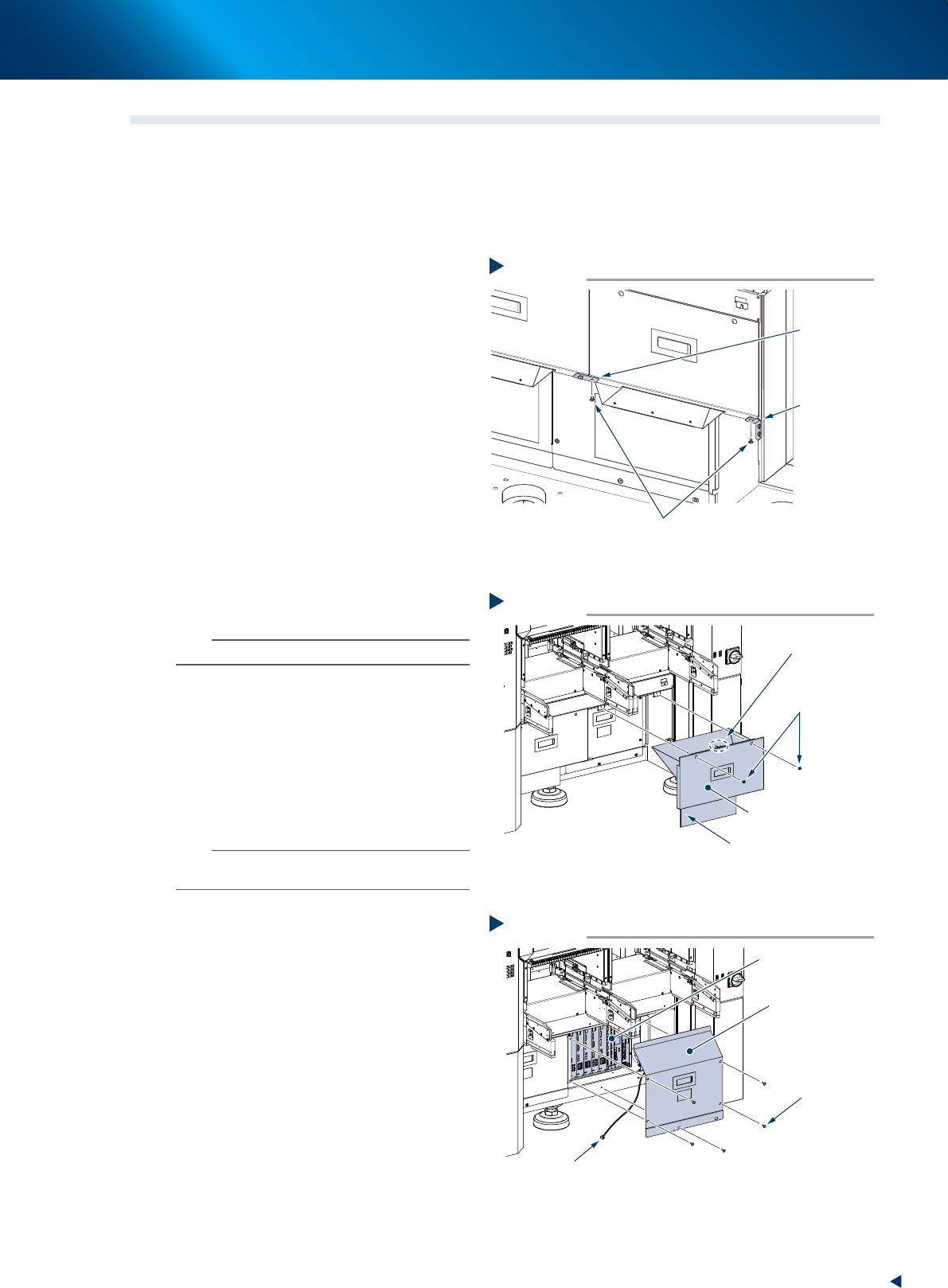
e
Prepare for work.
1. Press the emergency stop button and detach
the feeder exchange carriage of machine
front side.
2. Close applications and turn OFF the machine
power.
2
Remove the mounting screws installed
at left-right connecting point and
connecting point to machine body of
the safety cover (hereinafter referred to
as cutter cover) of tape cutter using
Phillips screwdriver.
3
Detach the cutter cover.
1. Remove the mounting screw (at front right of
machine front) using Phillips screwdriver.
2. Detach the cutter cover by pulling it out to
front.
n
NOTE
The cutter cover is installed an interlock key.
4
Detach the inner cover.
1. Remove 5 mounting screws of the inner
cover (front right) using Phillips screwdriver.
2. Detach the inner cover.
3. The ground wire is connected at the center
of the inner cover reverse side. Remove the
wire mounting screw using Phillips
screwdriver.
n
NOTE
The mounting screw of ground wire is used with a tooth
lock washer. Be careful not to lose it upon detaching.
5
Clean around the control box before
detaching the filter upon finding the
dust and dirt around the control box.
Removing the mounting screw
Step 2
Mounting screw
Left-right
connecting
point
Connecting
point to
machine body
53386-KMX-00
Step 3
Detach the cutter cover
Cutter cover (front right)
Mounting screw
Interlock key
Preventing cut debris splattering sheet
53380-KMX-00
Step 4
Detaching the inner cover
Inner cover
(front right)
Mounting screw
Control box
Ground wire mounting screw
53381-KMX-10