YRM20_Mainte_E.pdf - 第167页
Appe ndix Contents 1. S pe cifications ap-1 1. 1 A ir regulat or unit ap-1 1. 1.1 Supply air pre ssure ap-1 1.2 Power connection terminals ap-2 1.3 Connection be tween machines ap-3 1.3. 1 PREVIOU S INTERF A CE ap- 4 1.3…
5. Base
5-17
Chapter 5 How to replace consumable parts
►
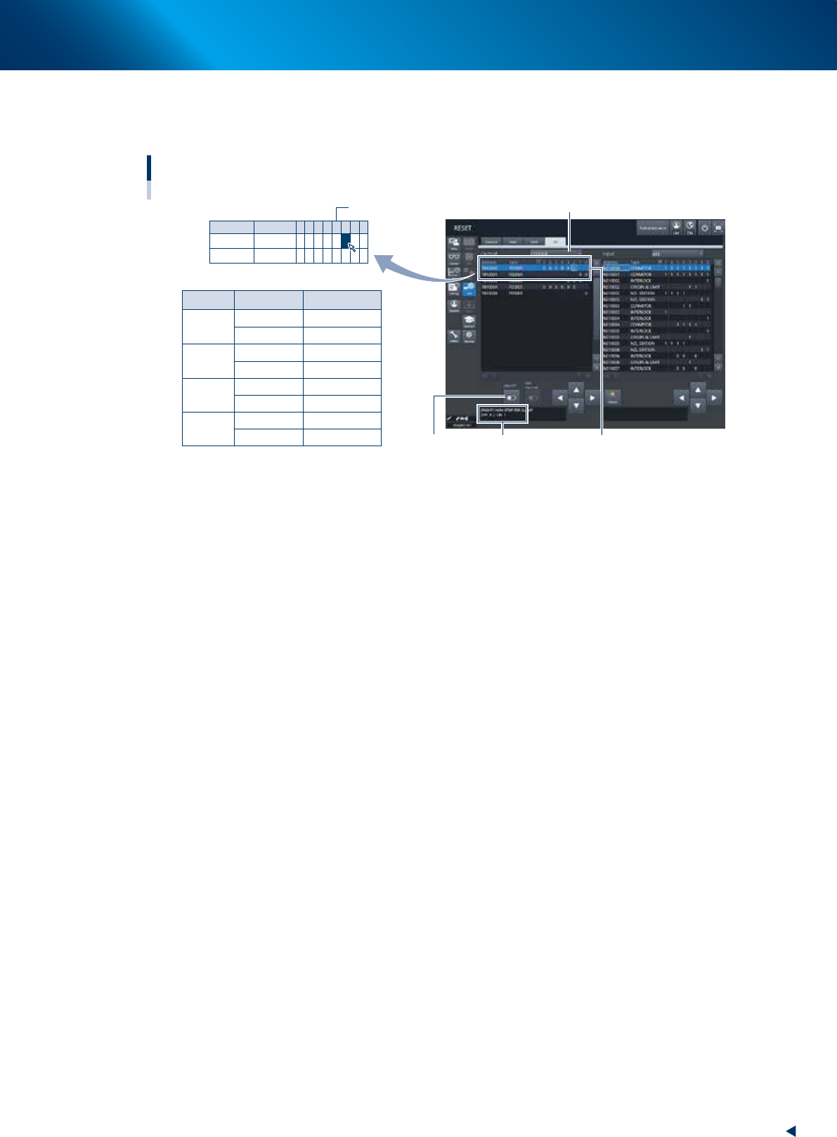
Valve operation check on the "I/O" screen
Perform the valve operation check on the "I/O" screen after the replacement of valve.
Checking carriage clamp valve operation
Reference
Select “FEEDER” from “Output”.
Select address.
Carriage Address
CLAMP
UNCLAMP
CLAMP
UNCLAMP
CLAMP
UNCLAMP
CLAMP
UNCLAMP
Description
T010000
T010000
T010000
T010000
T010000
T010000
T010001
T010001
-
-
-
-
-
-
-
-
2
3
4
5
3
5
0
1
[ON/OFF] button
Example: T010000 - 2
Address description
F1
F2
R1
R2
Address
T010000
T010001
Type
FEEDER
FEEDER
7
0
6
0
5
0
4
0
3
0
2
0
1
0
0
0
0
54505-KMX-00

Appendix
Contents
1. Specifications ap-1
1.1 Air regulator unit ap-1
1.1.1 Supply air pressure ap-1
1.2 Power connection terminals ap-2
1.3 Connection between machines ap-3
1.3.1 PREVIOUS INTERFACE ap-4
1.3.2 NEXT INTERFACE ap-5
2. YAMAHA Service website for user ap-6
3. Maintenance parts ap-7
3.1 YRM20 consumable parts list ap-7
3.2 YRM20 main unit maintenance parts list ap-8
1. Specifications
ap-1
Appendix
1. Specifications
1.1 Air regulator unit
1.1.1 Supply air pressure
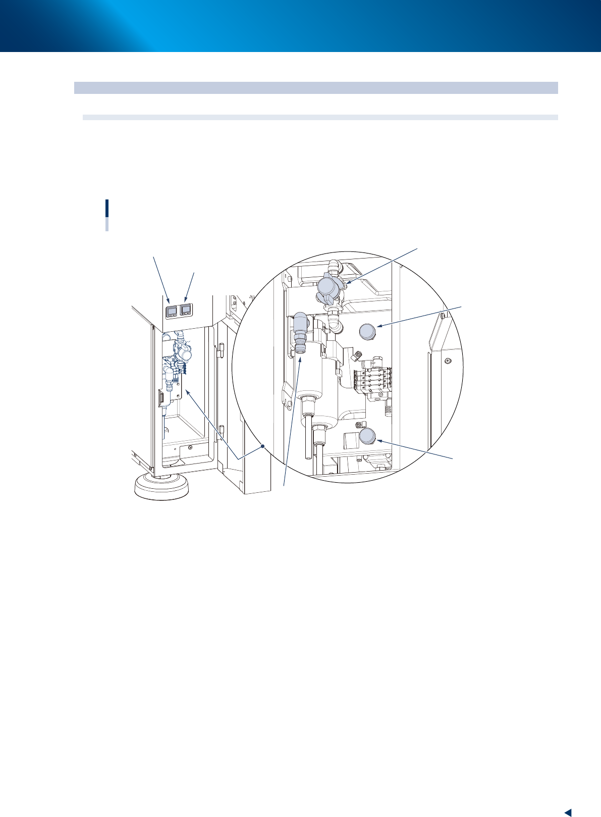
The air regulator for controlling the air pressure to the machine's pneumatic units is located at the lower left
panel on the front side of the machine. Specify the appropriate air pressure setting shown below.
Air pressure regulator section
Air supply/exhaust switch
Air pressure gauge (table B)
Air pressure gauge (table A)
Source air connector
Air pressure regulator
(table A)
Air pressure regulator
(table B)
53A01-KMX-00
►
Supply air pressure
This is the pressure of the source air supplied to the machine. Before setting the air pressure with the
air regulator, make sure that this supply air pressure is in the following optimal range.
YRM20 : 0.45MPa or more
►
Air pressure gauge
When within the normal range, the air pressure displays in green. When the air pressure is beyond
the upper/lower limit values (air down detection), an error occurs, and the air pressure displays in
red.
►
Set air pressure and air down detection
Set air pressure for main machine : 0.40MPa (0.39MPa~0.41MPa)
(When it achieves 0.45MPa, the air pressure gauge displays in
red.)
Air down detection pressure : 0.33MPa
►
Air supply/shutoff swith (valve)
Turning this switch to the right shuts off air supply and exhausts air that remains inside the machine.
►
Source air connector
Prepare an air hose with an inner diameter of at least 8 mm having a 40SH socket (Nitto Koki, or
equivalent), and connect it to this connector. Use dry, clean air passed through an air filter.