TS5322-user-guide.pdf - 第4页
4 2. UNPACKING AND INSPECTION Carefully unpack the valve and examine the items conta ined in the c arton. These will inclu de: • Valve asse mbly • Valve bracket an d air hose • Sample tip kit an d fluid line • User guide…
14
12. LIMITED WARRANTY
Manufacturer warrants this product to the original purchaser for a period of one (1)
year from date of purchase to be free from defects in material and workmanship,
but not against damages by misuse, negligence, accident, faulty installations and
instructions. Manufacturer will repair or replace (at factory’s option), free of
charge, any component of the equipment thus found to be defective, on return of
the component, “PREPAID” to the factory during the warranty period. In no event
shall any liability or obligation of the Manufacturer arising from this warranty
exceed the purchase price of the equipment. This warranty is only valid if the
defective product is returned as a complete assembly without physical damage.
The Manufacturer’s liability, as stated herein, cannot be altered or enlarged except
by a written statement signed by an officer of the company. In no event shall the
Manufacturer be liable for consequential or incidental damages. A return
authorization is required from Techcon Systems prior to shipping a defective unit
to the factory.
Manufacturer reserves the right to make engineering product modifications
without notice.
All returns must be issued with a Returns Authorization number, prior to return.
Send warranty returns to:
Americas and Asia
OK International
12151 Monarch Street
Garden Grove, Ca 92841
Europe
OK International
Eagle Close
Chandler’s Ford Ind Est
Eastleigh
Hampshire
SO53 4NF
United Kingdom
www.techconsystems.com
Teflon® is a registered trademark of E.I. DuPont.
TSI-0240_F
3
1. SPECIFICATIONS
TS5322 TS5322D
Size
4.0'' length X 1.12'' diameter
(102mm X 28mm)
4.0'' length X 1.12'' diameter
(102mm X 28mm)
Weight 0.31lb (139g) 0.26lb (119g)
Fluid Inlet Port ⅛'' NPT female ⅛'' NPT female
Fluid Outlet Port ⅛'' NPT female ⅛'' NPT female
Air Inlet Port 10-32 UNF 10-32 UNF
Auxiliary Air Inlet
Port
10-32 UNF 10-32 UNF
Minimum Air
Pressure
70 psi (4.8bar)
70 psi (4.8bar)
Maximum Fluid
Pressure
500 psi (34.5bar) 100 psi (6.9bar)
Operating
Frequency
Exceeds 500 cycles/min. Exceeds 500 cycles/min.
Mounting Port
¼-20 UNC-2B ¼-20 UNC-2B
Wetted Parts Type 303 SS, Al., Teflon®, EPR
Type 303 SS, Delrin®, Teflon®,
EPR
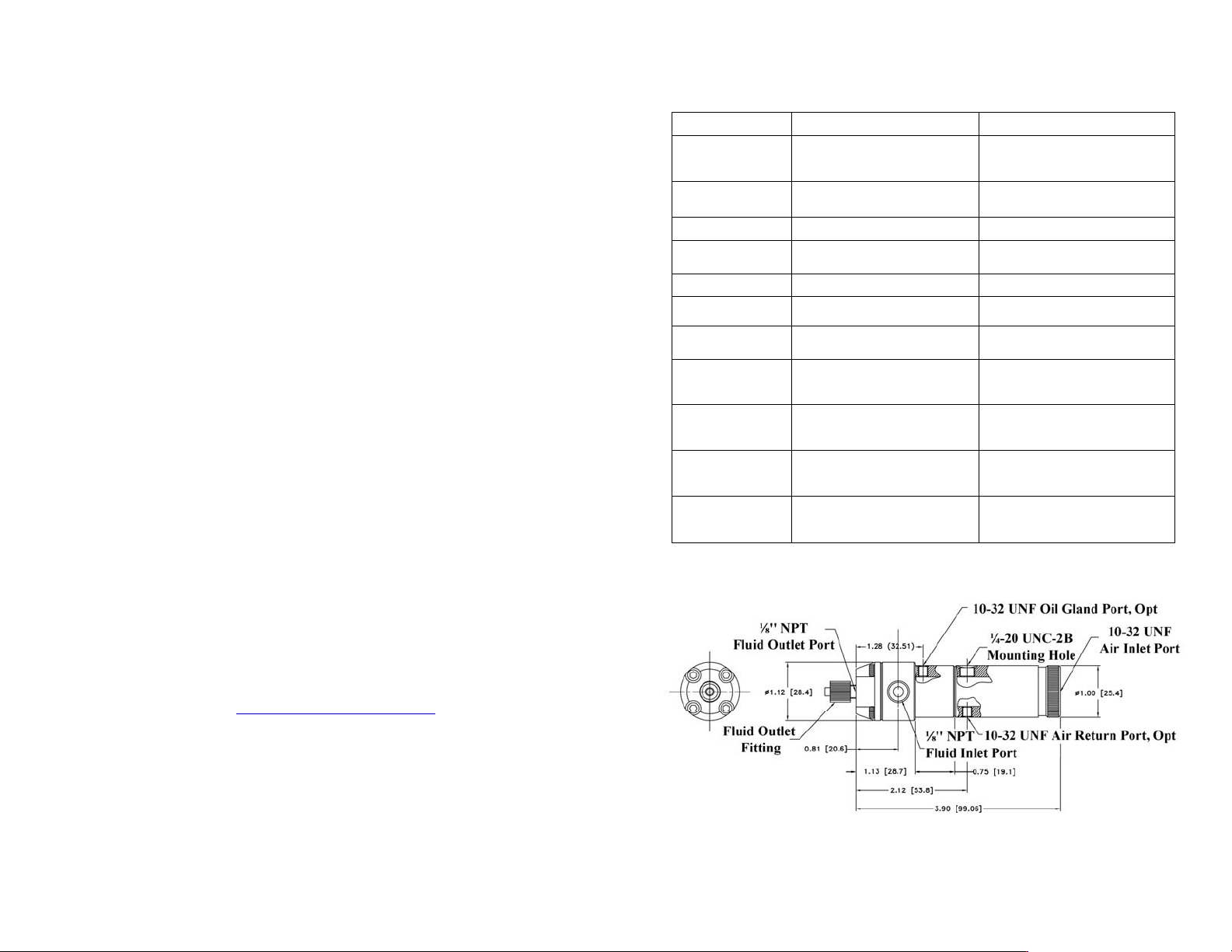
Fi
g
ure 1.0
Dimensions are in inches [mm]
4
2. UNPACKING AND INSPECTION
Carefully unpack the valve and examine the items contained in the carton.
These will include:
• Valve assembly
• Valve bracket and air hose
• Sample tip kit and fluid line
• User guide
3. DESCRIPTION
The TS5322 Series Mini Spool Valve is designed to dispense medium to high
viscosity fluids with very precise deposits, over a wide range of shot and bead
sizes. An internal spring return makes the valve fully adaptable for use with any
time/pressure controller. A short opening stroke provides extremely fast, positive
shut-off. An external adjustment makes it easy to fine tune “suck-back” level. The
TS5322’s compact design allows for mounting flexibility and easy integration into
automated applications.
4. THEORY OF OPERATION
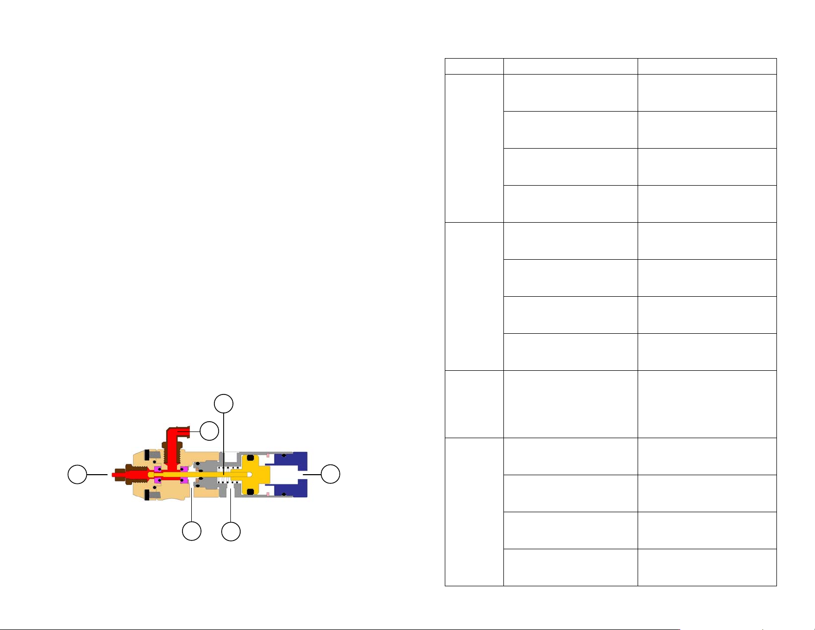
The TS5322 Series Mini Spool Valve is a normally closed spool valve with
adjustable “suck-back”. Input air pressure of 70 psi (4.8bar) through port (1)
drives the spool assembly (2) forward, opening the material path from the material
inlet (3) to the material outlet (4). Relieving the input air pressure allows the spool
assembly to travel back to the closing position, ensuring rapid “fail-safe” shut-off
of fluid flow
An oil chamber (5) is provided above the upper seal to create an additional liquid
seal that will prevent moisture from being carried on the spool. The auxiliary air
inlet port (6) is provided so that the valve may be connected for air closing with or
without the spring.
Figure 2.0
4
1
2
3
5
6
13
11. TROUBLESHOOTING
PROBLEM POSSIBLE CAUSE CORRECTION
No fluid
flow
Fluid pressure too low Increase fluid pressure
Operating pressure too low
Increase air pressure to 70 psi
(4.8bar)
Dispense tip clogged or
damaged
Replace tip
Fluid cured in valve chamber Clean valve thoroughly
Inconsistent
fluid flow
Fluid pressure fluctuating
Make sure fluid pressure is
constant
Valve operating pressure is too
low
Increased valve pressure to 70 psi
(4.8bar)
Valve open time is not consistent
Check to make sure the valve
controller is providing a
consistent output
Air trapped in fluid housing Purge valve
Fluid drools
after the
valve closes,
eventually
stopping
Air trapped in fluid housing Purge valve
Steady drip
Lower seal damaged or worn Replace lower seal
Spool damaged Replace spool
Inlet air fitting is too long,
pushing the spool opened
Replace air fitting
Valve re-assembled incorrectly
Re-assemble valve, follow re-
assembly instructions
12
10. STANDARD ACCESSORIES
10.1 OPTIONAL ACCESSORIES
10.2 FLUID FITTINGS AND TUBING
10.3 BRACKETS
PART NUMBER DESCRIPTION
TSD700-9 Oiler Cup, 90 Degrees
7305XCON Cleaning Gel, 30cc Syringe
PART NUMBER DESCRIPTION
TS918-46 4-Way Fluid Manifold
TN00DKIT Complete Dispensing Tip Kit
9000-000-100 Sample Tip Kit
5322-SIT Seal Insertion Tool
PART NUMBER DESCRIPTION
TSD1003-16 ⅛'' NPT to ¼'' O.D. Tube, 90° Elbow
TSD1002-17 ⅛'' NPT to ⅜'' O.D. Tube
TSD1002-18 ⅛'' NPT to ¼'' O.D. Tube
TSD1002-38 ¼'' NPT to ¼'' O.D. Tube
TSD1099-22 ⅜'' O.D. X ¼'' I.D. Tube, Black, Polyethylene
TSD1099-23 ⅜'' O.D. X ¼'' I.D. Tube, Clear, Polyethylene
TSD1099-24 ¼'' O.D. X ⅛'' I.D. Tube, Clear, Polyethylene
TSD1099-25 ¼'' O.D. X ⅛'' I.D. Tube, Black, Polyethylene
TSD1099-45 6mm O.D. X 4mm I.D, Clear, Polyethylene
TSD1099-46 6mm O.D. X 4mm I.D, Black, Polyethylene
TSD126-360BPK Luer Lock Tubing, 60'' (1524mm) , Black
PART NUMBER DESCRIPTION
918-033-000 Productions Master Stand (Base & Support)
918-000-012 Rod Clamp Assembly
1212-000-008 6'' (152.4mm) Threaded Mounting Rod
5
1
2
4
3
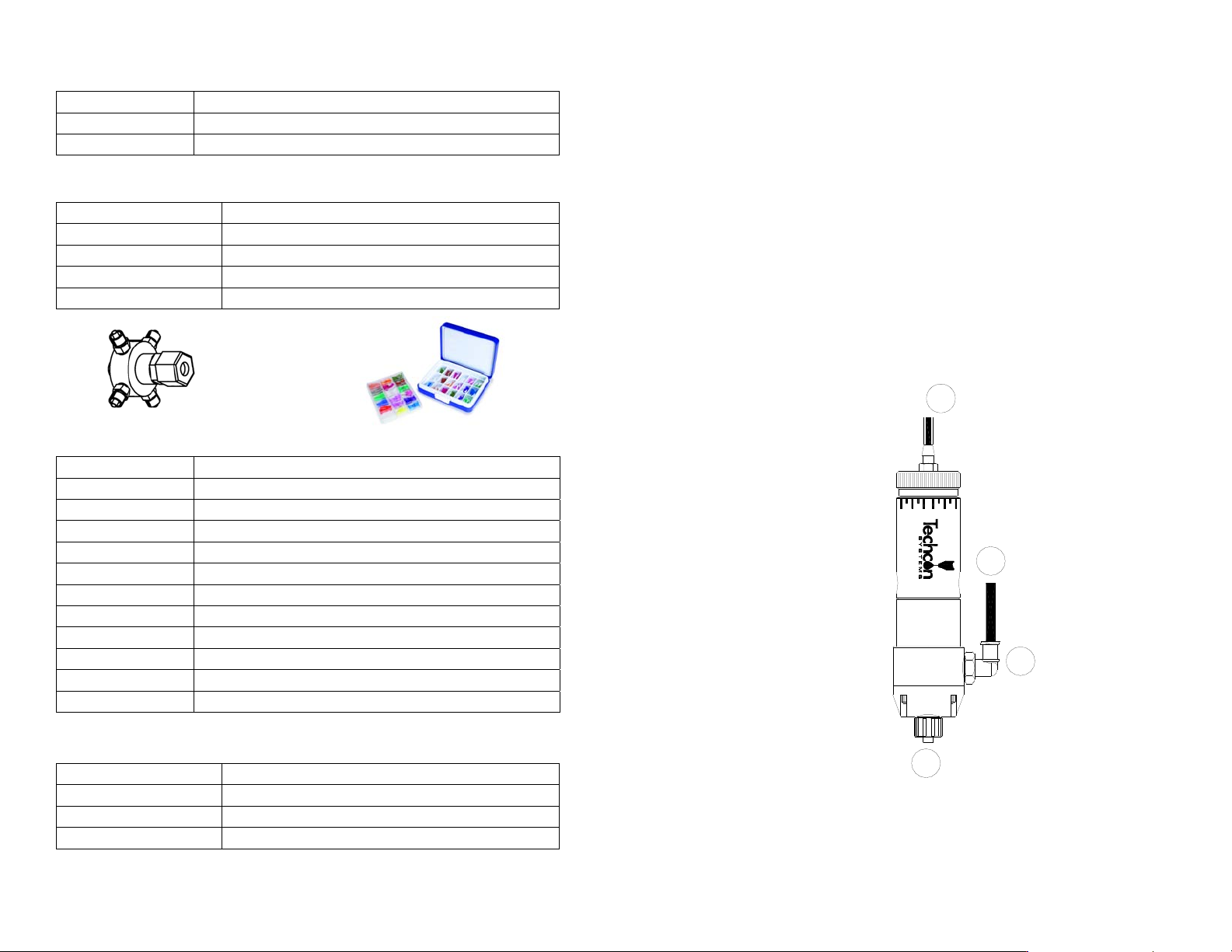
5. SET-UP INSTRUCTIONS
1. Connect the fluid reservoir feed tube (1) to the valve inlet port (2).
2. Connect the valve air hose (3) to the valve controller or other pneumatic device,
which is used to control the valve.
3. Connect an appropriate nozzle or dispensing tip (4) to the fluid outlet port.
4. Set the valve controller pressure at 70 psi (4.8bar).
5. Set the fluid reservoir pressure. Do not exceed 500 psi (34.5bar). For TS5322D,
do not exceed 100 psi (6.9bar).
6. Ensure all connections are tight.
7. Place container under the valve outlet and activate the valve until the fluid
flows steady.
The amount of fluid that flows through the valve is determined by:
• Valve open time
• Fluid reservoir pressure
• Dispensing tip size
Figure 3.0