TS5322-user-guide.pdf - 第8页
8 17. Insert o-ring (10) into outlet block (11). 18. Re-install outlet block (11) to fluid housing (6) . 19. Lubricate o-ring (17) with Bimba HT-99, or equiv alent. 20. Thread the air cylinder/spool assemb ly into fluid …
6
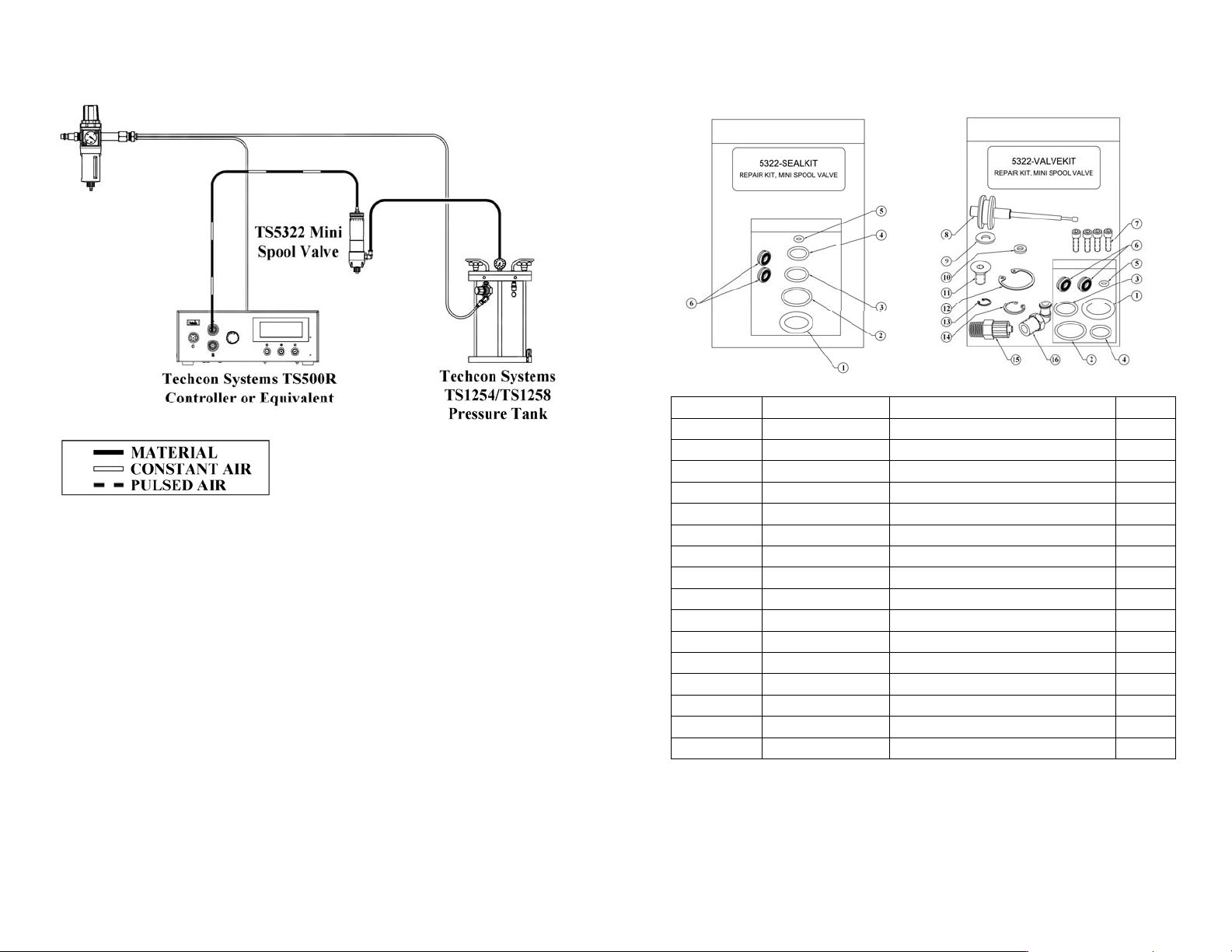
6. TYPICAL SYSTEM SET-UP
Figure 4.0
11
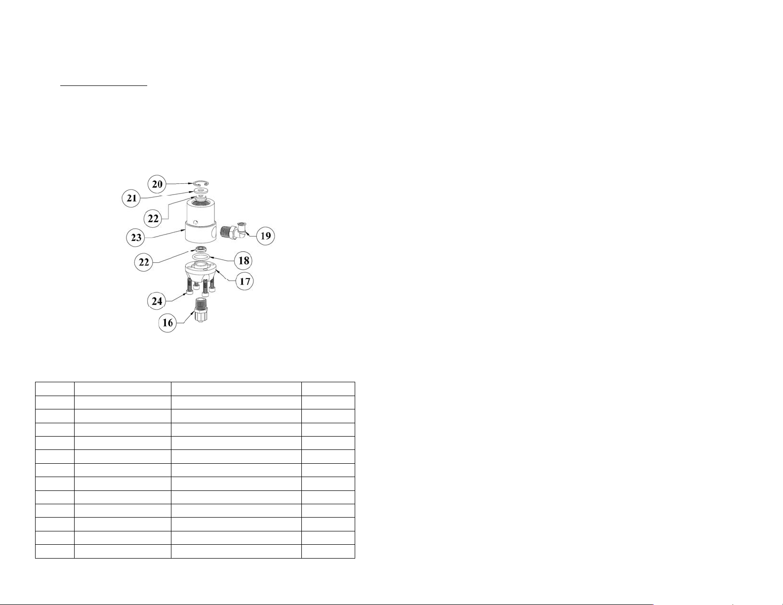
9. REPAIR KITS
*These kits are for both variations of Techcon Systems Miniature Spool Valve
ITEM PART NUMBER DESCRIPTION QTY
1 TSD1400-208A Piston O-Ring, Buna 1
2 TSD1400-017A End Cap, O-Ring, Buna 1
3 TSD1400-014A O-Ring, Buna 1
4 TSD1400-013A O-Ring, Buna 1
5 TD1400-006A O-Ring, Buna 1
6 TSD400-71 U-Cup Seal 2
7 TSD1103-349 Outlet Screw 4
8 5322-000-001 Spool/Piston Assembly 1
9 TSD1109-52 Flat Washer 1
10 TSD1109-45 Nylon Washer 1
11 TSD1106-36 Mounting Screw 1
12 TSD1120-15 Retaining Ring, Large 1
13 TSD1120-2 Retaining Ring, Small 1
14 TSD1120-6 Retaining Ring, Medium 1
15 TSD931-57 Luer Lock Adaptor 1
16 TSD931-75 Luer Lock Adaptor, Elbow 1
10
SPARE PARTS, CONT.
Valve Front Section
ITEM PART NUMBER DESCRIPTION QTY
16 TSD931-57 Luer Lock Adaptor 1
17 5320-000-001 Outlet Block For TS5322 1
17* 5320D-000-001 Outlet Block For TS5322D 1
18 TSD1400-014A O-Ring, Buna 1
19 TSD931-75 Luer Lock Adaptor, Elbow 1
20 TSD1120-6 Retaining Ring, Medium 1
21 TSD1109-52 Flat Washer 1
22 TSD400-71 U-Cup Seal 2
23 5320-000-002 Body For TS5322 1
23* 5320D-000-002 Body For TS5322D 1
24 TD1103-349 Outlet Block Screw 4
TSD700-9 Oiler Cup, Not Shown 1
Recommended lubricant:
All O-Rings & seals must be lubricated with Bimba HT-99, or equivalent, with
the exception of TSD400-71, which must remain dry.
7
7. MAINTENANCE AND CLEANING:
Tool required: O-ring removal tool (P/N TSD1597-7), snap ring pliers.
Normally, purging the valve with appropriate flushing material, or solvent after
use is sufficient for cleaning. However, some material may cause a build-up in the
valve chamber, in this case periodic and thorough cleaning will be required.
NOTE:
• Make sure the fluid pre ssure is re leased before valve is disassembled.
• To replace seals please order seal kit part number: 5322-SEALKIT.
• To repair valve please order valve kit part number: 5322VALVEKIT.
7.1 Cleaning and seal replacement for fluid housing: Refer to figure 5.0
1. Release fluid pressure.
2. Disconnect fluid line and remove fluid inlet fitting.
3. Disconnect valve air hose.
4. Hold the fluid housing (6) and rotate the air cylinder (18) counterclockwise.
When completely un-threaded, pull the two valve segments straight apart to
separate.
5. Inspect o-ring (17), replace if damaged.
6. Remove four socket head cap screws (12) from the outlet block (11).
7. Pull the outlet block (11) away from the fluid housing (6).
8. Inspect o-ring (10), replace if damaged.
9. Using snap ring pliers, remove retaining ring (8).
10. Remove stainless steel washer (9) from fluid housing (6).
11. Remove upper seal (14).
12. Clean the fluid housing (6), outlet block (11), spool assembly (5), upper and
lower seal (13) and (14).
NOTE: Avoid using sharp probes for cleaning. Any nicks or scratches on the
seal or the surfaces of the spool assembly may cause leakage
13. Inspect both upper (14) and lower seals (13), replace seals if damaged found.
14. Insert upper seal (14) into fluid housing (6) using the seal insertion tool 5322-
SIT. Make sure the o-ring side is facing down.
15. Insert stainless steel washer (9) and secure with retaining ring (8) using snap
ring pliers.
16. Insert lower seal (13) into outlet block (11). Make sure the o-ring side is facing
up.
8
17. Insert o-ring (10) into outlet block (11).
18. Re-install outlet block (11) to fluid housing (6).
19. Lubricate o-ring (17) with Bimba HT-99, or equivalent.
20. Thread the air cylinder/spool assembly into fluid housing/outlet block
assembly. Make sure not to cross thread both parts.
7.2 Cleaning and seal replacement for air cylinder:
1. Hold the fluid housing (6) and rotate the air cylinder (18) counterclockwise.
When completely un-threaded, pull the two valve segments straight apart to
separate.
2. Remove end cap (19) by rotating it in counterclockwise direction.
3. Using the snap ring pliers, remove the retaining ring (2).
4. Pull the spool assembly (5) straight out from the air cylinder (18).
5. Remove the compression spring (4).
6. Using the snap ring pliers, remove the retaining ring (7).
7. Remove the nylon washer (15) from the air cylinder.
8. Using o-ring removal tool, remove o-ring (16).
9. Replace all o-rings if necessary.
10. Lubricate all o-rings with Bimba HT-99, or equivalent.
11. Re-install o-ring (16).
12. Re-install nylon washer (15) and secure with retaining ring (7) Re-install
compression spring (4) into air cylinder (18).
13. Thread the air cylinder into fluid housing/outlet block assembly making sure
not to cross thread both parts.
14. Re-install spool assembly (5) and secure with retaining ring (2).
15. Re-install end cap (19).
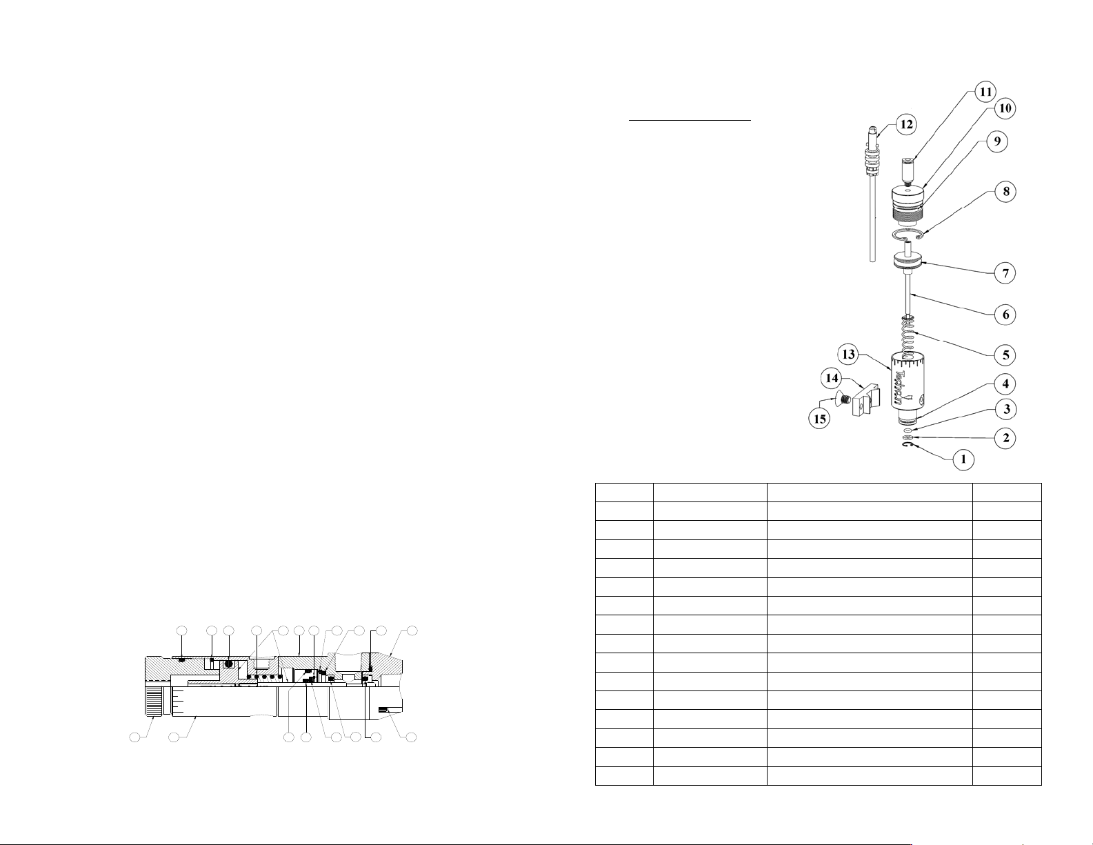
13 1219 18 17 16 15
123 5468791011
14
Figure 5.0
9
8. SPARE PARTS
Valve Rear Section
ITEM PART NUMBER DESCRIPTION QTY
1 TSD1120-2 Retaining Ring, Small 1
2 TSD1109-45 Nylon Washer 1
3 TD1400-006A O-Ring, Buna 1
4 TSD1400-013A O-Ring, Buna 1
5 TSD1150-5 Spring 1
6 5322-000-001 Spool/Piston Assembly 1
7 TSD1400-208A Piston O-Ring, Buna 1
8 TSD1120-15 Retaining Ring, Large 1
9 TSD1400-017A End Cap O-Ring, Buna 1
10 5520-000-007 End Cap 1
11 TSD1002-37 Air Fitting, 4mm 1
12 A0100478 Air Hose/Connector Assembly, 4mm 1
13 5520-000-001 Air Cylinder 1
14 918-000-048 Mounting Bracket 1
15 TSD1106-36 Mounting Screw 1
Recommended lubricant:
All o-rings & seals must be
lubricated with Bimba HT-99,
or equivalent.