P-0277-004.pdf - 第6页
MEMO

MODEL CU-G300L/R
0712-002
CONT-1
目 次
CONTENTS
Fig. DC
カッタ部
DC CUTTER SECTION DC
Fig. DC-1
フレーム部
Base Frame
Fig. DC-2
駆動部
Driving Section
Fig. DC-3
カッタ部
Cutter Section
Fig. DC-4
レバー部
Lever Section
Fig. DD
カッタ部
DD CUTTER SECTION DD
Fig. DD-1
ベースフレーム
Base Frame
Fig. DD-2
駆動部
Driving Section
Fig. DD-3
カッタ部
Cutter Section
Fig. DD-4
レバー部
Lever Section

MEMO
MODEL CU-G300L
0712-002
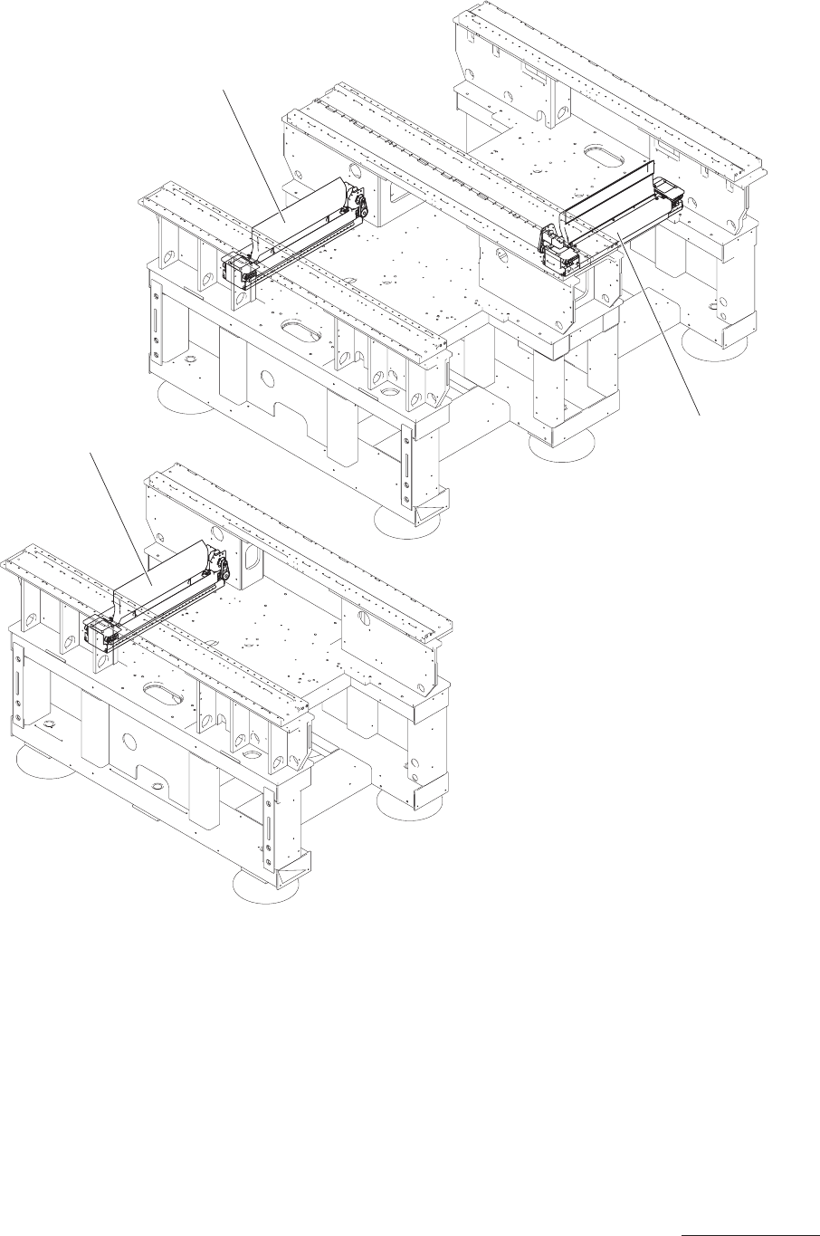
Fig. DC
カッタ部
DC CUTTER SECTION DC
BLOCK1
注1)
BLOCK4
注2)
GXH-3
2 UNIT / 1 MACHINE
注1)BLOCK1に多段トレイが装着する場合、BLOCK1のカッタユニットは
削除となります。(G-S014-12)
注2)BLOCK4に多段トレイが装着する場合、BLOCK4のカッタユニットは
削除となります。(G-S014-15)
Notice 1)
When the Multi-Layer Tray Feeder is attached to the BLOCK1,
the cutter unit of BLOCK1 is deleted.(G-S014-12)
Notice 2)
When the Multi-Layer Tray Feeder is attached to the BLOCK4,
the cutter unit of BLOCK4 is deleted.(G-S014-15)
GXH-3J
1 UNIT / 1 MACHINE
BLOCK1
注1)
DC illust-1