00198352-01_AI_Conveyor_Conversion_Kit_E-by-SIPLACE_EN.pdf - 第27页
Assembly Instructions E by SIPLACE Conveyor Conversion Kit 03/2017 4 Software Installation 4.3 SIPLACE Pro Machine and Line Configuration Setup 27 4.3 SIPLACE Pro Machine and Line Configuration Setup After hardware conve…
4 Software Installation
4.2 Stopper and Board sensor functional check
Assembly Instructions E by SIPLACE
Conveyor Conversion Kit 03/2017
26
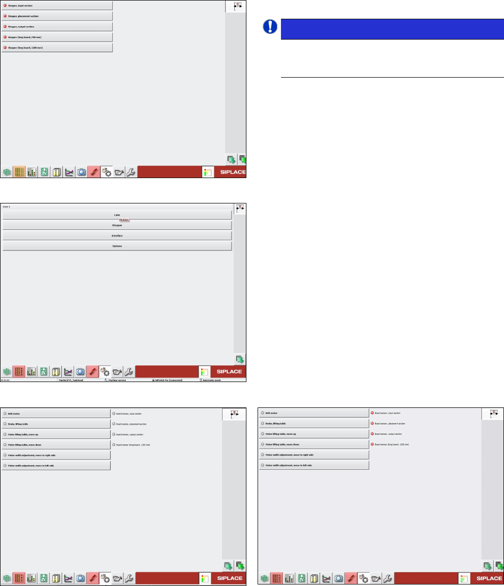
Fig.16: Checking stoppers
All stopper activated with red indication.
NOTICE!
Check and confirm that the stopper units on
the stopper set are in extended up position
according to the right sequence.
.
► If any stopper does not activate when enabled,
check the wiring connection and stopper condi-
tion.
Fig.17: Checking board sensors
► Check board sensor condition.
Go to Lane selection.
Fig.18: Board sensor condition without PCB
Fig.19: Board sensor condition when sensor is covered by
PCBs
► Perform complete machine calibration and mapping for machine after all stoppers and board
sensors are in good working condition.
Assembly Instructions E by SIPLACE
Conveyor Conversion Kit 03/2017
4 Software Installation
4.3 SIPLACE Pro Machine and Line Configuration Setup
27
4.3 SIPLACE Pro Machine and Line Configuration Setup
After hardware conversion, SIRIO station software and Machine calibration proceed with machine
and line configuration on SIPLACE Pro:
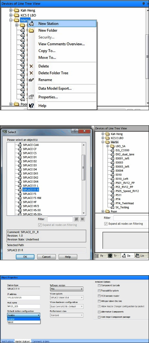
Fig.20: New Station
Step 1:
► Under station line tree view select New Station.
Fig.21: Select conveyor type
Step 2:
► Select SIPLACE E1 R for right fixed conveyor.
► Select SIPLACE E1 L for left fixed conveyor.
Fig.22: Object Properties
Step 3:
► Input the machine IP address, Host name.
Choose Default station configuration (Speed
or Flexible) and Software version.
4 Software Installation
4.3 SIPLACE Pro Machine and Line Configuration Setup
Assembly Instructions E by SIPLACE
Conveyor Conversion Kit 03/2017
28
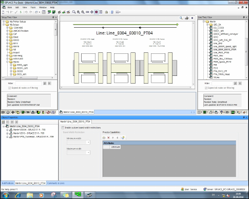
Fig.23: Example consisting of three machines
Step 4:
► Setup line configuration as per machines setup.