Nordson-EFD-794-Operating-Manual.pdf - 第7页
794 Series Auger Valve | Operating Manual 7 www.nordsonefd.com info@nordsonefd.com +1-401-431-7000 Sales and service of Nordson EFD dispensing systems are available worldwide. Packing List The following items are include…
794 Series Auger Valve | Operating Manual
6 www.nordsonefd.com info@nordsonefd.com +1-401-431-7000 Sales and service of Nordson EFD dispensing systems are available worldwide.
Specifications
NOTE: Specifications and technical details are subject to engineering changes without prior notification.
Item Specification
Size 237.5 mm length x 31.8 mm diameter (9.35 x 1.25")
Weight 544.0 g (19.2 oz)
Auger speed (dry) 250–500 RPM based on voltage input
Auger pitch 8, 16
Input voltage 10–24 VDC (<10% ripple)
Maximum acceleration 2.0 g (0.07 oz)
Maximum continuous current 240 mA
Input air pressure 0–2.07 bar (0–30 psi)
Maximum fluid pressure 2 bar (30 psi)
Fluid inlet 304 stainless steel, #10-32 UNF x 5/32"
Optional push-in fitting: Polypropylene
Mounting 10-32, low profile
Fluid body 440C hardened stainless steel
Auger 440C hardened stainless steel
Approvals China RoHS
All stainless steel parts are passivated.
RoHS标准相关声明标准相关声明 (China RoHS Hazardous Material Declaration)
产品名称
Part Name
有害物质及元素
Toxic or Hazardous Substances and Elements
铅
Lead
(Pb)
汞
Mercury
(Hg)
镉
Cadmium
(Cd)
六价铬
Hexavalent
Chromium
(Cr6)
多溴联苯
Polybrominated
Biphenyls
(PBB)
多溴联苯醚
Polybrominated
Diphenyl Ethers
(PBDE)
外部接口
External Electrical
Connectors
X 0 0 0 0 0
O: 表示该产品所含有的危险成分或有害物质含量依照EIP-A, EIP-B, EIP-C
的标准低于SJ/T11363-2006 限定要求。
Indicates that this toxic or hazardous substance contained in all the homogeneous materials for this part, according to EIP-A, EIP-B, EIP-C is below the
limit requirement in SJ/T11363-2006.
X: 表示该产品所含有的危险成分或有害物质含量依照EIP-A, EIP-B, EIP-C
的标准高于SJ/T11363-2006 限定要求.
Indicates that this toxic or hazardous substance contained in all the homogeneous materials for this part, according to EIP-A, EIP-B, EIP-C is above the
limit requirement in SJ/T11363-2006.
794 Series Auger Valve | Operating Manual
7www.nordsonefd.com info@nordsonefd.com +1-401-431-7000 Sales and service of Nordson EFD dispensing systems are available worldwide.
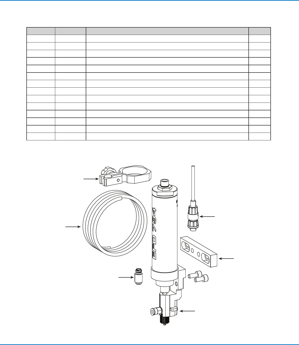
Packing List
The following items are included with the 794 auger valve.
Item Part # Description Qty.
1 — Fitting, 4 mm push-in to luer 1
2 7016761 Urethane tubing, 0.3 m (1 ft) 1
3 — Barrel clamp and knob 1
4 7021981 Brush-motor valve cable 1
5 7021960 Mounting bar and screws 1
6 — 794 valve assembly 1
Not shown 7016129 Adapter, 10cc, 1.8 m (6 ft) 1
Not shown 7016134 Adapter, 30cc, 1.8 m (6 ft) 1
Not shown 7012526 Standard high flow kit (optional stainless steel kit available) 1
Not shown 7019147 8 g valve purge compound 1
Not shown 7021996 794 valve tip kit 1
Not shown — Dot Test Kit Sheet 3
Not shown — Valve purge compound Safety Data Sheet (SDS) 1
Not shown — Valve purge instructions 1
2
3
4
1
5
6
794 Series Auger Valve | Operating Manual
8 www.nordsonefd.com info@nordsonefd.com +1-401-431-7000 Sales and service of Nordson EFD dispensing systems are available worldwide.
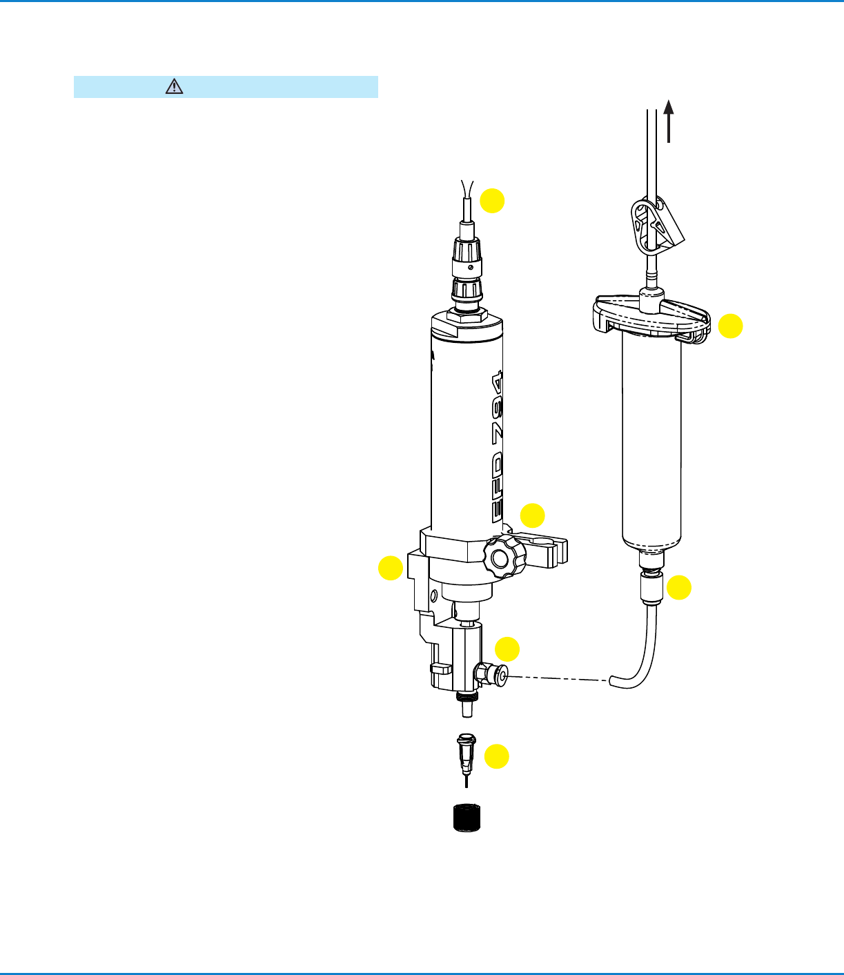
Installation
WARNING
Disconnect the electrical power and inlet air pressure
to the factory automation system and valve controller
prior to proceeding.
1. Mount the valve securely to the Z-axis of the
robot using the bracket provided for the valve or
another appropriate mounting bracket for other
machines.
2. Connect the motor wires to the valve controller.
The white wire connects to the (+) terminal and
the brown wire to the (–) terminal.
3. Attach the barrel outlet fitting to the end of a
barrel of material to be dispensed.
4. Insert the barrel into the barrel clamp, position as
required, and clamp securely.
5. Trim a length of the supply hose provided to
approximately 80 mm (3 1/8") and push into the
barrel outlet and auger assembly input fittings.
6. Attach the blue end of the barrel adapter
assembly to the end of the barrel. Connect the
bayonet fitting to the valve controller air output.
7. Install an EFD 1/4" long dispensing tip of the
appropriate gauge. (Refer to “Changing a Tip” on
page9.)
White
Valve mounting
bracket
To regulated
air supply
Adapter
assembly
Brown
Motor wires
Fluid inlet
fitting
Barrel outlet
fitting
Fluid supply
tubing
Dispensing tip
Barrel
clamp
Motor
chamber
1
2
3
4
5
6
7
Making Adjustments
Dispense time is the primary method of making small
adjustments in deposit size. In general, larger deposits
require longer dispense times, larger diameter tips,
and larger gaps. Be sure to allow settling time (before
dispense) and dwell time (after dispense). Very small
deposits may require chamfered tips. Air pressure
should be set to a point just below where drooling
occurs without the auger turning.