Nordson-EFD-794-Operating-Manual.pdf - 第9页
794 Series Auger Valve | Operating Manual 9 www.nordsonefd.com info@nordsonefd.com +1-401-431-7000 Sales and service of Nordson EFD dispensing systems are available worldwide. Changing the Auger Assembly 1. Do the follow…
794 Series Auger Valve | Operating Manual
8 www.nordsonefd.com info@nordsonefd.com +1-401-431-7000 Sales and service of Nordson EFD dispensing systems are available worldwide.
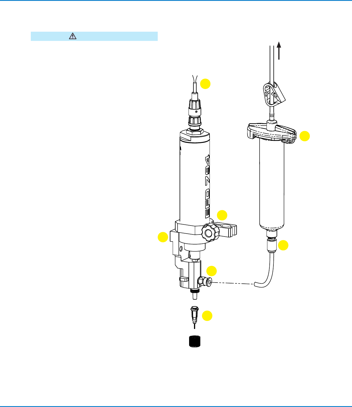
Installation
WARNING
Disconnect the electrical power and inlet air pressure
to the factory automation system and valve controller
prior to proceeding.
1. Mount the valve securely to the Z-axis of the
robot using the bracket provided for the valve or
another appropriate mounting bracket for other
machines.
2. Connect the motor wires to the valve controller.
The white wire connects to the (+) terminal and
the brown wire to the (–) terminal.
3. Attach the barrel outlet fitting to the end of a
barrel of material to be dispensed.
4. Insert the barrel into the barrel clamp, position as
required, and clamp securely.
5. Trim a length of the supply hose provided to
approximately 80 mm (3 1/8") and push into the
barrel outlet and auger assembly input fittings.
6. Attach the blue end of the barrel adapter
assembly to the end of the barrel. Connect the
bayonet fitting to the valve controller air output.
7. Install an EFD 1/4" long dispensing tip of the
appropriate gauge. (Refer to “Changing a Tip” on
page9.)
White
Valve mounting
bracket
To regulated
air supply
Adapter
assembly
Brown
Motor wires
Fluid inlet
fitting
Barrel outlet
fitting
Fluid supply
tubing
Dispensing tip
Barrel
clamp
Motor
chamber
1
2
3
4
5
6
7
Making Adjustments
Dispense time is the primary method of making small
adjustments in deposit size. In general, larger deposits
require longer dispense times, larger diameter tips,
and larger gaps. Be sure to allow settling time (before
dispense) and dwell time (after dispense). Very small
deposits may require chamfered tips. Air pressure
should be set to a point just below where drooling
occurs without the auger turning.
794 Series Auger Valve | Operating Manual
9www.nordsonefd.com info@nordsonefd.com +1-401-431-7000 Sales and service of Nordson EFD dispensing systems are available worldwide.
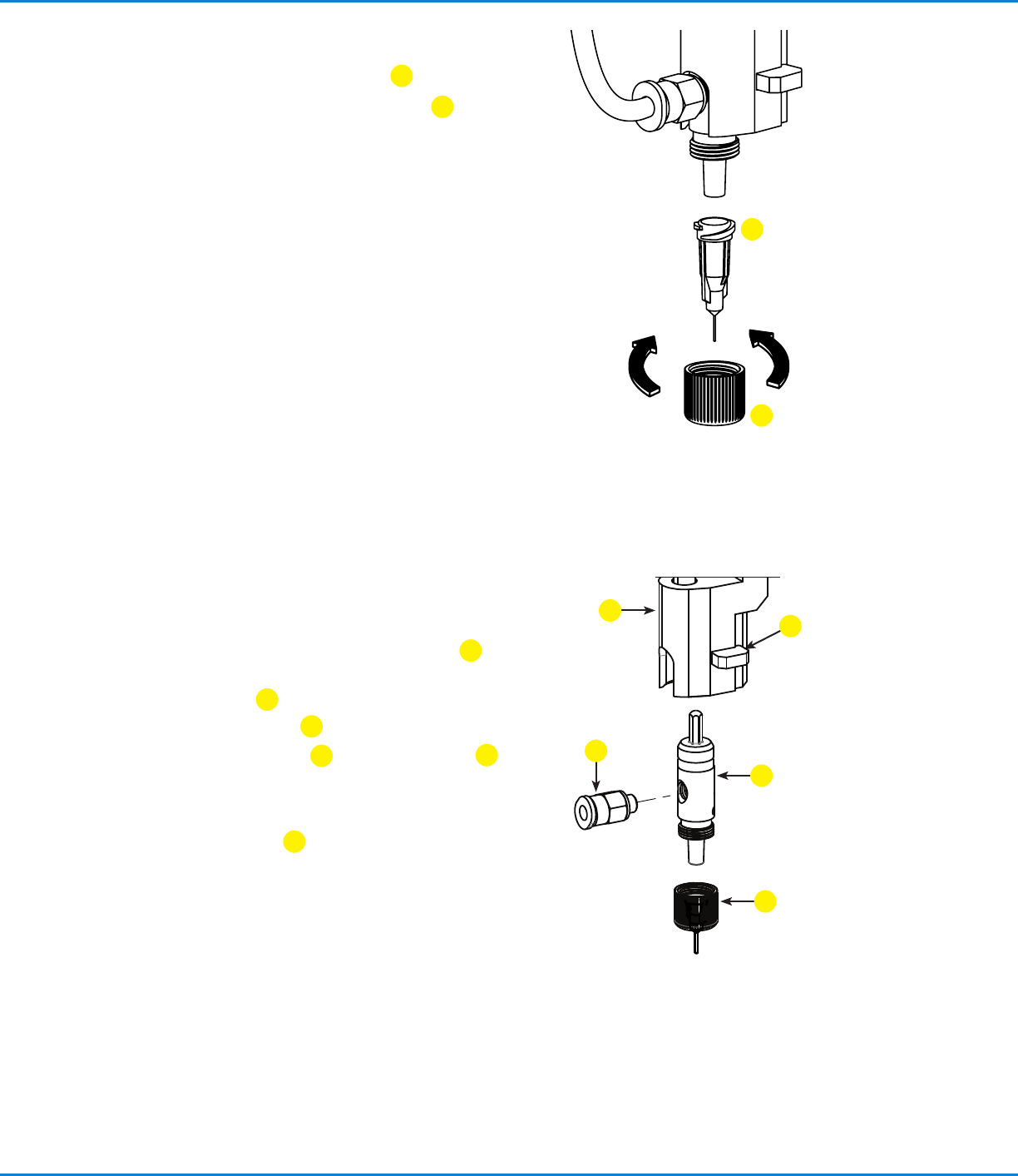
Changing the Auger Assembly
1. Do the following to disconnect the fluid supply:
a. Loosen the barrel clamp.
b. Raise the barrel.
c. Disconnect the tubing from the fluid inlet fitting
5
and pull it out through the slot in the clamp.
2. Push back the lever
2
on the valve fluid body.
The entire auger assembly
3
drops out of the fluid body.
3. Remove the fluid inlet fitting
5
and tip/retaining nut
4
from the auger assembly and install these components on
the replacement auger assembly.
4. Insert the hex drive of the replacement auger assembly
into the valve fluid body
1
, rotate the auger assembly
until the hex engages, and then push up until the auger
assembly snaps into place.
5. Reconnect the fluid supply and restore the barrel and
barrel clamp to the normal operating position.
Changing a Tip
1. Loosen and remove the tip retaining nut
1
.
2. Remove the tip and install the replacement tip
2
(1/4"only).
3. Reinstall and tighten the tip retaining nut.
NOTES:
• To ensure proper axial location of the tip, tighten the cap
on the fine-adjust assembly until it bottoms out firmly
against the end of the auger assembly.
• Use only EFD 1/4" long tips, tip sizes 7018029 through
7018462. Refer to the EFD Precision Dispense Tip Sheet
for available gauge sizes and dimensions.
1
2
2
3
4
1
5

794 Series Auger Valve | Operating Manual
10 www.nordsonefd.com info@nordsonefd.com +1-401-431-7000 Sales and service of Nordson EFD dispensing systems are available worldwide.
Solder Paste
Nordson EFD’s comprehensive line of ISO-certified solder paste solutions include high quality printing and dispensing
soldering pastes that meet the most stringent application requirements. Visit www.nordsonefd.com/SolderPlusPaste for
details or to request a free sample.
Service
Refer to the 794 Service & Replacement Parts Manual for service procedures.
Valve Part Numbers
Part # Pitch Model Description
7029745 8 794-FR Auger valve, 8 pitch, brush motor, fixed head
7029746 16 794-FR Auger valve, 16 pitch, brush motor, fixed head
Replacement Parts
Refer to the 794 Service & Replacement Parts Manual for replacement parts.