BA-PM200-english-D08851.pdf - 第3页
1. Description, Operating Conditions The pumps transfer, and evacuate 100 % oil-free. In operation they are gas- tight, and maintenance-free. The self drying pumps make it possible during evacuation to blow the conden- s…
0. List of Contents
1. Description, Operating
Conditions
2. Safety
3. Installation
4. Operation
5. Servicing
6. Trouble Shooting
7. Ordering Information
8. Specifications
You have selected a high-quality KNF product; the following tips will help you operate it safely, and reliably over
a long period of time.
Carefully study operating instructions before using the pumps and observe at all times the relevant instructions
to avoid dangerous situations.
PM 16633-842.3
Operating Instructions
PM 16633-842.3
Self Drying Pumps
Laboratory Vacuum Pumps
with Drying System
INNOVATIVE
TECHNOLOGY
WORLDWIDE
1. Description,
Operating Conditions
The pumps transfer, and evacuate 100
% oil-free. In operation they are gas-
tight, and maintenance-free.
The self drying pumps make it possible
during evacuation to blow the conden-
sed liquid out of the pump heads at
high speed, while maintaining the
vacuum in the recipient at a constant
level. After drying the pump heads the
pumps achieve a greatly improved
vacuum and evacuate much faster
than pumps without a drying system.
The control for the drying system is
effected via soleonid valve and three
variables:
The time between switching on the
drying system and the first ventila-
tion of the pump heads (t
1
)
The duration of the ventilation of
the pump heads (t
2
)
The interval between pump head
ventilation operations (t
3
).
This pump model is equipped with the
solenoid valve for ventilating the pump
heads. The scope of delivery does not
include control electronics.
1.1 Electrical Equipment
See section 8 for full electrical
data.
The pumps are fitted with a thermal
-switch to protect against over-
loading.
1.2 Operating Conditions
The pumps and/or the drying
system must not be used in
areas where there is a danger of
explosion.
These pumps must not be used if
the entry of air into the pump
during venting (drying system)
could result in the creation of reac-
tive, explosive or otherwise hazar-
dous mixtures.
Prior to any use of the pump en-
sure that the creation of reactive,
explosive or otherwise hazardous
mixtures during the supply of air is
prevented.
For maximum permissible operating
pressure, ultimate vacuum, and
flow capacity: see chapter 8.
The pumps must not be used for
liquids. You will find suitable liquid
pumps in our Product Program.
If your potential application lies outside
the above limits discuss it with our
technical adviser (see last page for
contact telephon number).
1.3 Ambient Condition
When the pumps are operating the fol-
lowing ambient conditions must be
maintained:
The pumps and/or the drying
system must not be used in
areas where there is a danger of
explosion.
Ambient temperature during opera-
tion: between + 5 °C .... + 40 °C.
During operation an adequate
supply of air for cooling must be
provided.
2. Safety
Note that the pumps may only be
used for their intended purpose.
The pumps and/or the drying
system must not be used in
areas where there is a danger of
explosion.
These pumps must not be used if
the entry of air into the pump
during venting (drying system)
could result in the creation of reac-
tive, explosive or otherwise hazar-
dous mixtures.
Prior to any use of the pump en-
sure that the creation of reactive,
explosive or otherwise hazardous
mixtures during the supply of air is
prevented.
Components connected to the
pumps must be designed to with-
stand the pneumatic performance
of the pumps (see chapter 8).
Plug the pump only into properly
installed grounded outlets.
When the operation of the pump is
interrupted by the thermal switch, it
will re-start automatically after
cooling down. Take all care neces-
sary to prevent this leading to a
dangerous situation.
Specific safety instructions and
measures for the media being
handled must be observed.
Parts of the casing marked with the
sign below are only allowed to be
opened after pulling out the plug
(disconnecting the power source).
Use only original KNF replacement
parts.
3. Installation
Choose a safe location (flat sur-
face for the pump).
Install the pump so as to ensure
adequate flow of air cooling.
Connect the suction and pressure
lines (tube ID 10 mm).
Arrange the pressure line so
that condensate can flow out
of the the pump (falling pipe).
The condensate is conducted out
of the pump via the pressure line.
A container is to be installed to
catch the condensate.
The solenoid valve must be
connected to the drying system
control electronics (not included in
scope of delivery); see fig. 1.
Plug the pump only into properly
installed grounded outlets.
Compare the supply data with the
elecetrical data of the pump. The
voltage must not vary by more than
+ 10 %, and -10 % from that shown
on the type-plate.
4. Operating Instructions
4.1 Operating Conditions
The pumps and/or the drying
system must not be used in
areas where there is a danger of
explosion.
These pumps must not be used if
the entry of air into the pump
during venting (drying system)
could result in the creation of reac-
tive, explosive or otherwise hazar-
dous mixtures.
Prior to any use of the pump en-
sure that the creation of reactive,
explosive or otherwise hazardous
mixtures during the supply of air is
prevented.
Specific safety instructions for the
media being handled must be
observed.
PM 1633-842.3-3.00 e 11/05 Symbols: = Position in the illustration, = Important point, = Task, = Advise to users, Warning KNF resrve the right to make changes
2
The pumps must not start against
pressure. This also applies when
the pump restarts after the power
has been cut off for a short period.
The components to be connected
to the pump must be designed to
withstand the pneumatic data of
the pumps (see Section 8).
The maximum permissible opera-
ting pressure (1 bar g) must not be
exceeded.
To prevent the maximum permis-
sible operating pressure being
exceeded, restriction or control of
the air or gas flow should only be
carried out in the suction line.
If restriction or control of the air or
gas flow is made on the pressure
side ensure that the maximum per-
missible operating pressure is not
exceeded.
When the pump is at a standstill
the inlet and the outlet must be at
normal atmospheric pressure.
Ensure the pump outlet is not clo-
sed or restricted.
Diaphragm and valve plates are the
only parts subject to wear. Wear is
usually indicated by a drastic
reduction in the pneumatic perfor-
mance. When replacing parts pro-
ceed as described in section 5.
Ambient conditions: see chapter
1.3.
4.2 Operation
Taking the pump into operation
Plug the mains plug of the pump
into a properly installed safety
socket.
Switch the pump on at the pump
mains switch (see fig. 1).
If cyclic drying of the pump heads
is required in the current evacu-
ation process, switch the drying
system on at the mains switch of
the control (not included in
scope of delivery).
The drying system should only
be switched on if a container
has been attached to the pres-
sure line of the pump which will
catch the condensate; other-
wise the condensate will flow
out uncontrolled.
Check:
Tubing for correct tubing.
Electrical connections for correct
connection.
After the evacuation/process has been
completed, take the pump out of ope-
ration:
Purge the pump including the
connecting hoses with air at full
flow rate for about 5 minutes.
If the drying system is switched
on:
Switch the drying system off at the
mains switch of control system
(not included in scope of delivery).
Switch the pump off at the mains
switch of the pump.
Pull the mains plug of the pump out
of the socket.
5. Servicing:
Changing Diaphragms and Valve
Plates/Sealings
The structured diaphragms in both
pump heads should be changed at the
same time. When diaphragms are
changed, valve plates/sealings should
also be replaced. If the diaphragms are
not changed in both heads at the same
time or diaphragms and valve plates/
sealings are not changed at the same
time the nominal performance of the
pump is not guaranteed after the servi-
ce.
If a pump has been used for
aggressive or toxic substances or
other types of substances which
are hazardous, hazardous to health,
or injurious, the following points
must be observed:
1.) Clean the pump and its compo-
PM 1633-842.3-3.00 e 11/05
3
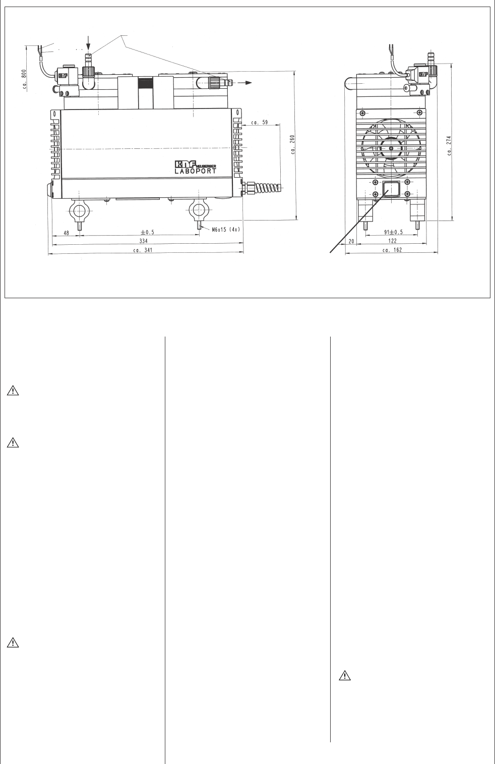
Fig. 1: Pump PM 16633-842.3-3.00
Mains switch
for tube ID 10
Valve voltage 24 V DC
blue (-)
brown (+)
231