BA-PM200-english-D08851.pdf - 第6页
second pump head. e.) Refitting the pump heads At one pump head: Press the lip on the edge of the structured diaphragm into the groove in the housing. Place the intermediate plate , with the valve plates/sealings…
nents before servicing.
2.) Ensure that the service personnel
is not subject to a health hazard.
Apply the safety and protection
measures that are necessary for
the medium that has been handled
by the pump (example: the use of
protective gloves).
3.) Ensure that discarded parts and
materials are safely and correctly
disposed of.
Use only original KNF replacement
parts.
Required tools and material:
Service Set (see section 7)
Philips-head screwdriver No. 2.
Change the structured diaphragms and
valve plates/sealings in the following
sequence:
a.) Preparatory steps
b.) Remove pump heads
c.) Change structured diaphragms
d.) Change valve plates/sealings
e.) Refit pump heads
f.) Final steps.
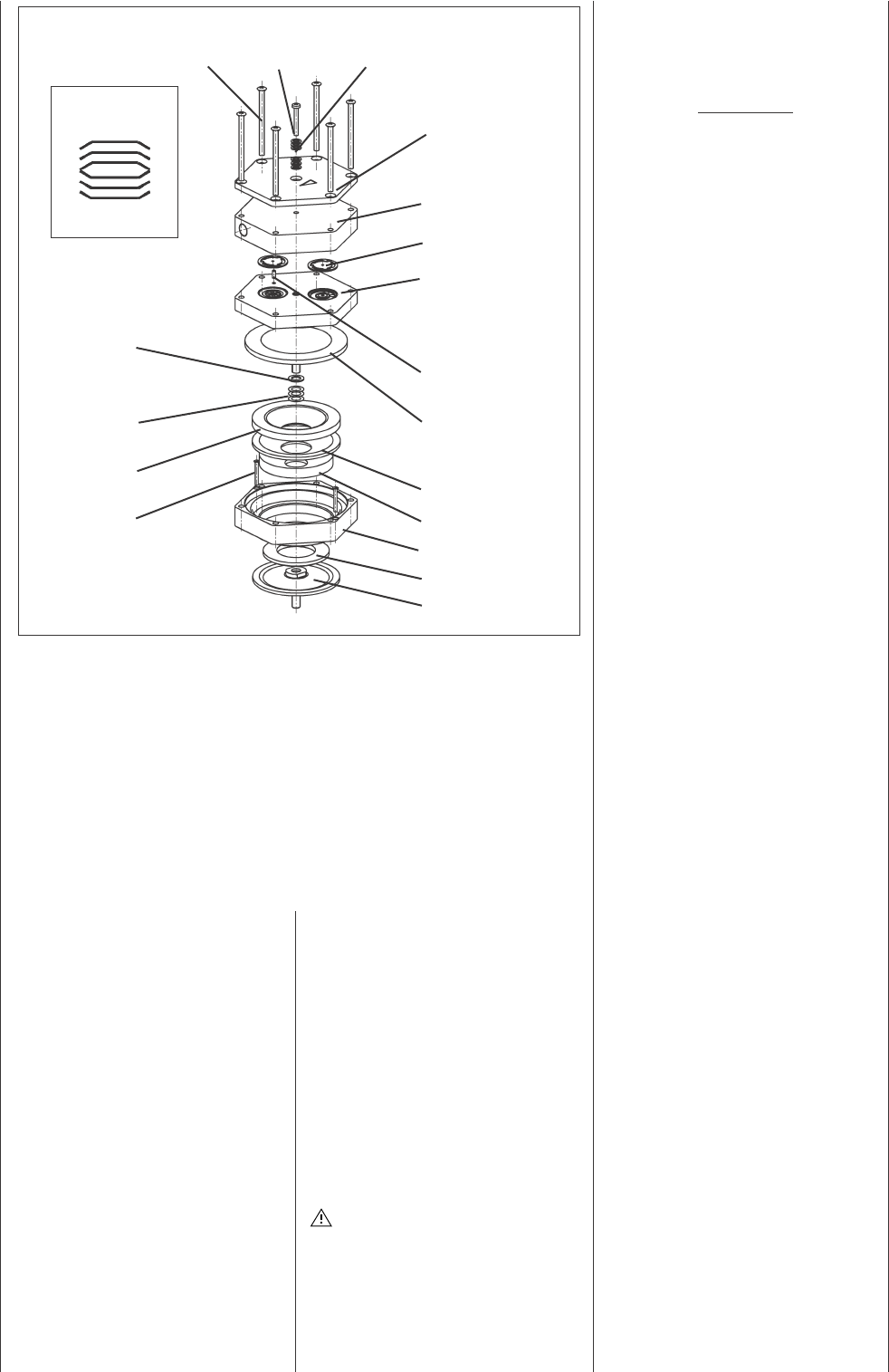
The postion numbers in the fol-
lowing text refer to fig. 2.
a.) Preparatory Steps
Shut down system (see section 4.2)
including disconnecting the pump
from the power source (pull out
plug of electrical supply unit).
Remove tubing from the inlet and
outlet connectors of the pump.
b.) Removing the pump heads
On the pneumatic head connec-
tions, loosen one of the union nuts
by hand. Then slightly loosen the
angle-fitting in the pump head by
turning it anticlockwise
, so that the
connecting tube can be pulled out.
Loosen the outer screws on
eachpump head.
Carefully remove both pump heads
(top plate , head plate and
intermediate plate ).
The soleonid valve of the
drying system remains fitted
in this situation.
c.) Change structured diaphragms
Push down one structured dia-
phragm until other diaphragm is
pushed upwards to its highest
position.
Carefully unscrew the higher
strucutred diaphragm anti-clock
wise using both hands.
Replace all spacers / onto the
screw thread of the new structu-
red diaphragm (same number and
order)
Screw in the new structured dia-
phragm and tighten it by hand;
you do not need any tool.
Change the second structured dia-
phragm as described above (step
to ) for the first.
Changing the two diaphragms one
after the other ensures that the
same number of diaphragm spa-
cers are refitted as were removed.
This is essential to maintain the
pneumatic performance of the
pump.
d.) Change valve plates/sealings
Unscrew the three screws in
the top plate of one pump head.
Carefully remove top plate and
head plate from intermediate
plate ; exposing the valve pla-
tes/sealings .
Remove old valve plates/sealings
.
If there should be deposits in the
recesses in the intermediate plate
, clean them until the deposits
have been completly removed.
Insert new valve plates/sealings
in the recesses in the interme-
diate plate (upper and lower
sides of the valve plates/sealings
are identical).
Carry out the steps to for the
PM 1633-842.3-3.00 e 11/05
4
Specification
Screw (12x)
Screw (3x)
Disk spring
Top plate
Head plate
Valve plate/sealing
Intermediate plate
Guide pin
Structured diaphragm
Spacer (thick)
Spacer (thin)
Dampening ring A
Screw
Dampening felt
Dampening ring B
Adapter
Dampening ring C
Dampening
diaphragm
Orientation of disk
springs
Fig. 2: Pump head for N 842.3_ (exploded drawing, symbolic)
Pump N 842_ has a round shape of head

second pump head.
e.) Refitting the pump heads
At one pump head:
Press the lip on the edge of the
structured diaphragm into the
groove in the housing.
Place the intermediate plate ,
with the valve plates/sealings on
the adapter .
Place the head plate on the
intermediate plate in the posi-
tion indicated by the guide pin .
Place the top plate on the head
plate in the right position.
Gently tighten screws in diago-
nal order.
Screw in the three screws in
the centre of the pump top plate
until they are flush with the top
plate; then screw one final half
turn to tighten.
For orientation of disk springs
see fig. 2.
Carry out steps to for the
second pump head.
! Refit the pneumatic head connec-
tion:
Place tube onto the connecting
part of the angle fitting, turn angle
fitting to a straight position and
tighten the union nut.
f.) Final steps
Reconnect system tubing.
Reconnect the pump to the electri-
city supply.
If the pump does not reach the
desired vacuum after changing
diaphragms and valve plates/sea-
lings:
Check whether the spacers have
been replaced onto the diaphragm
screw thread.
Check the interconnecting pipe-
work connection between both
pump heads as well as the tubing
for leaks.
Possibly the screws on one of
the pump heads (or both heads)
are insufficiently tightened
(carefully tighten them again
crosswise).
If you have any questions about
servicing call our technical adviser
(see last page for contact tele-
phone number).
6. Troubleshooting
Sufficient vacuum is not reached
Possible reasons:
Tube connections are not tight
Condensate in the pump head
Switch the drying system on
or reduce the interval bet-
ween pump head ventilation
operations.
Diaphragms and/or valve plates/
sealings are worn out
Changing diaphragms and
valve plates/sealings: see
section 5.
If this problem occurs after chan-
ging of diaphragms or valve pla-
tes/sealings:
See information in section 5.
Pump is switched on, but does not
run, the on/off-switch on the pump
is not lit
Possible reasons:
Pump is not connected with the
power source.
No voltage in the power source.
Fuse in the pump is defective (only
authorized/qualified personnel
should investigate this problem):
Disconnect the pump from
the power source by pulling
out plug.
Placement of fuse:
The fuse is accessible after
opening the marked cover at
the bottom of the pump.
Dimension of the fuse:
see section 8.
Pump is switched on, but does not
run, the on/off-switch on the pump
is lit
Possible reason:
The thermal switch has opened
due to overheating
Disconnect the pump from
the power source, let the
pump cool down, investigate
the reason for the overhea-
ting and irradicate it.
7. Ordering Information
Service Set
A Service Set contains all
replacement parts needed for one
complete service of the pump.
Service Set contains
2 diaphragms and 4 valve plates/
sealings
Order No.
057359
8. Specifications
Capacity: max. 34 l/min
Ultimate vacuum: 4 mbar abs
Permissible opera-
ting pressure: max. 1 bar
g
Permissible ambient
temperature: +5... +40°C
Hose connection for tube ID 10 mm
Voltage pump: 230 V
Frequency: 50 Hz
Power consum-
ption pump: 220 W
Fuse pump
(2 x): 3.15 T [A]
IP 44
Voltage soleonid
valve 24 V DC
CE - Safety Demands
The pumps correspond to the
safety regulations of the EU low
voltage directive 73/23 EWG and of
the EU directive concerning elec-
tromagnetical compatibility 89/336
EWG. The requirements of the fol-
lowing harmonised standards are
fulfilled:
EN 55014
EN 61000-6-1
EN 61000-6-3
EN 61000-3-2/3
EN 61010-1
The pumps correspond to IEC 664:
the overvoltage category II
the pollution degree 2.
PM 1633-842.3-3.00 e 11/05
5

Appendix:
Customer statement for
repair order (sample
statement for copying)
In order for KNF to repair the
pump, the customer must provide
a statement on the media which
were pumped and on pump
cleaning. Please fill out the cor-
responding KNF form, and submit
it together with the pump.
Statement/Certificate
We confirm that the pump
model listed below
(please specify)
.............................................
.............................................
.............................................
Serial-No. (please specify)
.............................................
.............................................
.............................................
was used to pump the fol-
lowing media:
.............................................
.............................................
.............................................
.............................................
.............................................
.............................................
.............................................
and that the pump listed
above was cleaned. There
are no poisonous, aggres-
sive, biological, radioac-
tive or other dangerous
media in the pump.
................ ......................
Company Date/
Signature
PM 1633-842.3-3.00 e 11/54
KNF Neuberger GmbH
Alter Weg 3
D-79112 Freiburg
Tel. ++49/7664/5909-0
Fax ++49/7664/5909-99
E-Mail: info@knf.de
www.knf.de