KE-301020VA_E.pdf
High-Speed Chip Shooter High-Speed Flexible Mounter KE-3010AM/KE-3010AL/KE-3010XL KE-3020VAM/KE-3020VAL/KE-3020VXL A A A A A Lite A Oct-2017/Rev .06 Whit e list (s tan dard) Viru s meas u rem ents oftware
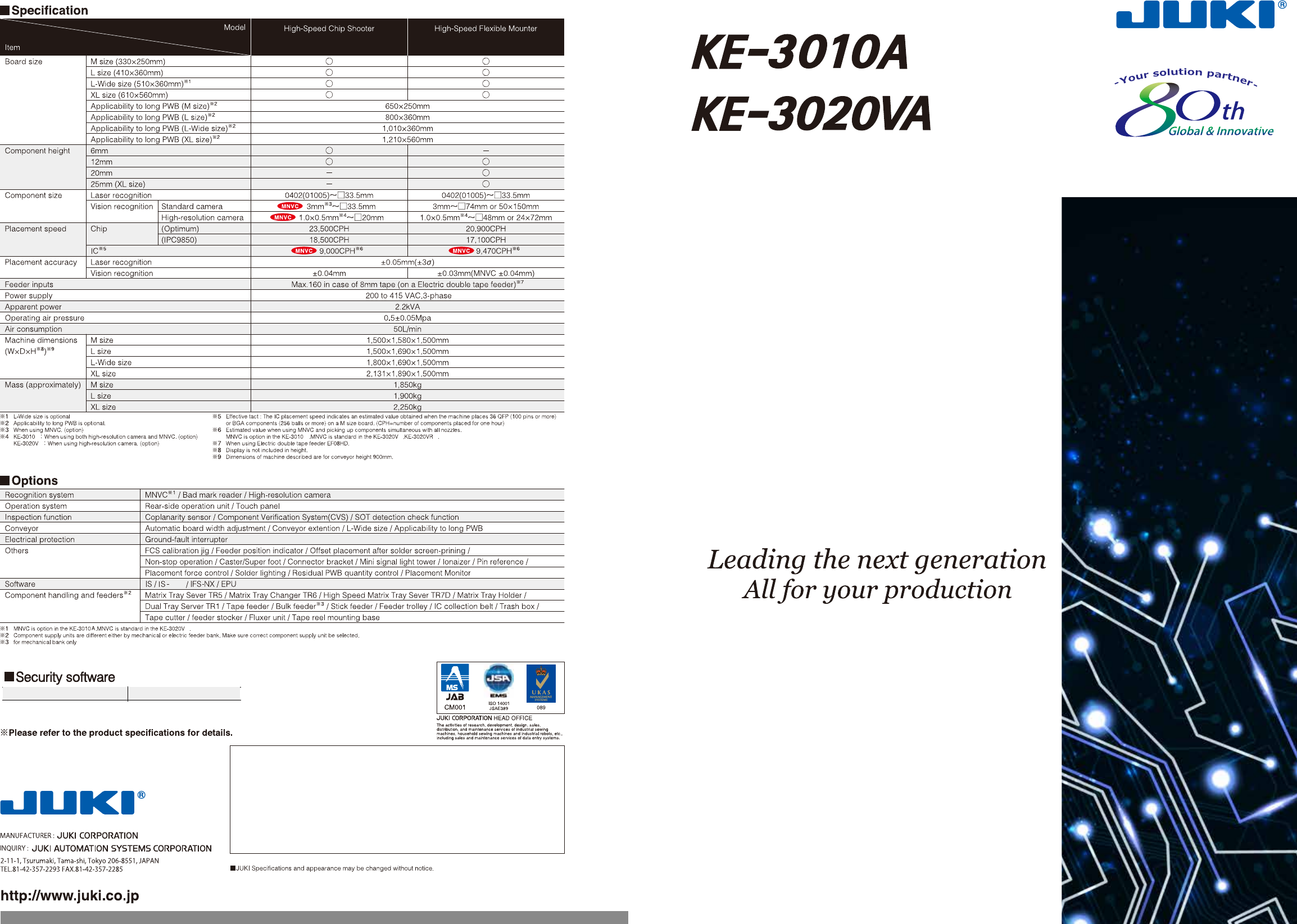
High-Speed Chip Shooter
High-Speed Flexible Mounter
KE-3010AM/KE-3010AL/KE-3010XL KE-3020VAM/KE-3020VAL/KE-3020VXL
A
A
A
A
A
Lite
A
Oct-2017/Rev.06
White list (standard)
Virus measurementsoftware
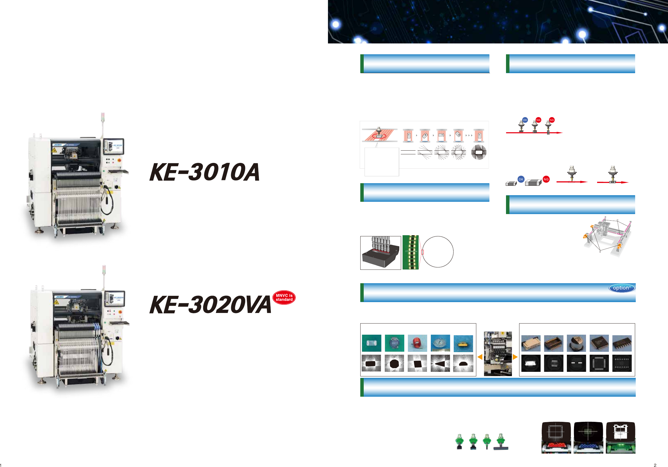
For placement of ultra-small components
◎23,500CPH chip (Laser centering/Optimum)
◎18,500CPH (Laser centering / IPC9850)
◎9,000CPH IC(Vision centering/MNVC option)
◎One multi-nozzle laser head (6 nozzles)
◎From 0402(01005)to 33.5mm square components
◎Supported PWB size: M/L size
For placement of large / odd-shaped components
◎20,900CPH chip (Laser centering/Optimum)
◎17,100CPH chip (Laser centering / IPC9850)
◎9,470CPH IC(Vision centering/MNVC)
◎From 0402(01005) to 74mm square components or 50×150mm
◎Vision centering system (featuring bottom, side, and back lighting,
all ball recognition and split recognition)
◎Supported PWB size: M/L size
KE-3020VA
◎One multi-nozzle laser head (6 nozzles) plus
one IC head with CDS sensor (1 nozzle)
KE-3010A
High speed flexible mounter
responding to various expectation
- from ultra-small components
to odd-shaped components.
1.JUKI Basic Technology
The machine can recognize components of various
shapes: from an ultra miniature components such
as 0402 (01005) chips up to 33.5mm square
components such as PLCCs, SOPs, BGAs, and
QFPs. When the machine recognizes a component
with laser, variations such as shape, color, and
reflection do not matter.
Recognition algorithm
Laser calculates the
following
data for each
component:
component shape
Center Angle Width
Each nozzle has independent Z and theta control
for superior flexibility, accuracy, and redundancy.
The height and angle of each nozzle can be
controlled precisely.
Highly-precise
placement angle is
possible using
servo motors
②
Component state check
Compare the dimensions and ratio
of component data to the
component picked for confirmation
of pick orientation.
③
Component
dimension check
Compare the dimensions of
the part picked to the
component data to ensure
the right part is picked.
④
Component fall check
Laser checks if the
component falls
before placement.
⑤
Release check
Laser checks if the
component is properly
released on the board
after placement.
The component check function improves the quality
of component placement. Component presence is
monitored by the laser from pick to placement,
reducing the chance for missing components.
X-Y drive system features
JUKI's original "full closed
loop control" using AC motors
and magnetic linear encod-
ers.
Both X and Y axis keeps
high-speed, and highly
reliable
placements intact.
Full closed loop control
Vision recognition
Laser recognition
Vision centering technology
Centering method can be selected based on component type, shape, size and material. Laser centering is
used for high-speed placement of smaller components. Vision is used when lead or ball inspection is needed
or when the component is too large for the laser. Many nozzles are available for odd-shaped components
providing unsurpassed component handling.
Bottom and side
recognition
Bottom and side
recognition
Back light
recognition
①Linear encoders
②AC motors
JUKI laser centering for flexibility and quality
※PWB size XL will be KE-3010
※PWB size XL will be KE-3020V
KE-3020VA
Independent Z and theta-axes control
※Vision centering is available on the KE-3010A with the MNVC option.This function is standard on the KE-3020VA .
The component check function improves the
quality of component placement.
①On-the -fly component detection
Laser detects presence of components.
Laser Laser
Laser
0402chip
MNVC(Multi Nozzle Vision Centering)
Vision centering by the multi-nozzle head nearly doubles the placement rate for smaller components, including
CSPs, BGAs and smaller QFPs.
Nozzles for odd-shaped components
High-Speed Chip Shooter
High-Speed Flexible Mounter
Easy operation
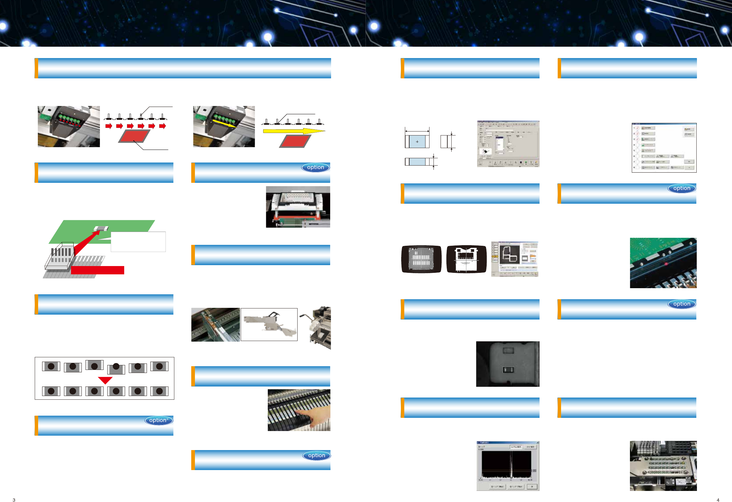
Ease-of-operation improved by
automatic component measurement
Component data can be programmed simply by
typing approximate dimensions, type and packag-
ing information. Accurate dimensions, number of
leads and lead pitch are measured and
programmed automatically by the machine.
This function assists operators in the preparation of
a new production. By simply following a checklist of
setup items from “1. Automatic width adjustment” to
“8. Production program check,” an operator can be
sure they have performed the necessary steps and
see which have not been completed.
Non-stop Operation
Non-stop operation allows the operator to replace
feeders while the machine continues to run at full
speed.
160 component inputs
Up to 160 different components can be installed on
the machine for ultimate flexibility. The feeder
trolley has no cables or hoses to connect for
ultra-fast, ultra accurate change-overs.
Simple setting of feeder pitch
No tools are required to
change the feeder pitch.
Pitch is set using buttons
on the feeder.
High precision and quality placement
with Electronic feeders
Flexible vision teaching
Complicated programming of odd-shaped compo-
nents is made easier by following step-by-step
guidelines, reducing programming time significantly.
Automatic correction of pick position
※
The position error information of a nozzle is transmit-
ted to each electric feeder so that each electric
feeder automatically adjusts feeding for more stable
pick position and for better simultaneous picks.
Automation Nozzle Changer (ATC)
Automatically replace nozzles according to
component dimensions.
Auto teaching of pick position reduces changeover
time and mis-picks.
Auto Teaching of Pick Position
Centering errors prevented
by self check
Laser contamination is checked prior to the produc-
tion. If contamination is detected, an alarm is given
to prevent centering errors.
High-speed, on-the-fly vision centering
dual upward looking strobing cameras capture images in high speed for large, fine pitch, or odd-form compo-
nents.
【existing recognition】
pause for each component recognition
nozzle
camera
【non-stop Vision recognition】
non-stop recognition for each component
component
Simultaneous on-the-fly component
2 centering for high-speed production
Feeder Position Indicator
Feeder Position Indicator
LED's on the feeder bank indicates which feeder
needs to be replaced or which feeder has an alarm,
indicates location of feeders to be set during change
over, and helps simplify feeder setup.
High-resolution Camera
Enable high-accurate
inspection for components
like QFP with lead pitch 0.2
mm.
Tape Cutter
※
Automatically cuts used tape and stores it in an
easily removable trash bin, eliminating mess and
decreasing operator workload.
Rear-side Operation Unit
Allows complete machine operation from the rear
Adjustment side of the machine.
※Only available on electrical feeder
2.High Productivity
ATC unit(Auto-Tool Changer)
VCS unit
(Vision Centering System)
Trolley set up image
EF08HDRSingle & double lane feeder
Component data is updated
after automatic measurement.
check list
Flexible vision teaching
Laser contamination check
※Option for mechanical feeder specification, standard for electrical feeder specifica-
tion.
Laser sensor is integrated into the placement head
for on-the-fly centering. Head moves directly from
the pick position to the placement position for the
shortest possible head travel and maximum place-
ment speed.
Head moves directly
from the pick to the
placement position
Laser sensor integrated
into placement head
Component
dimensions:
Width
Depth
Height