TS1212.pdf - 第3页
5 5. SET UP INSTRUCTIONS Refer to Figure 3.0 1. Install a new pinch tube in the valve. Follow ing instructions in Section 6. “Pinch tube replacement” on page 8. 2. If desired, moun t the valve to the bracket inc luded. 3…
3
1. SPECIFICATIONS
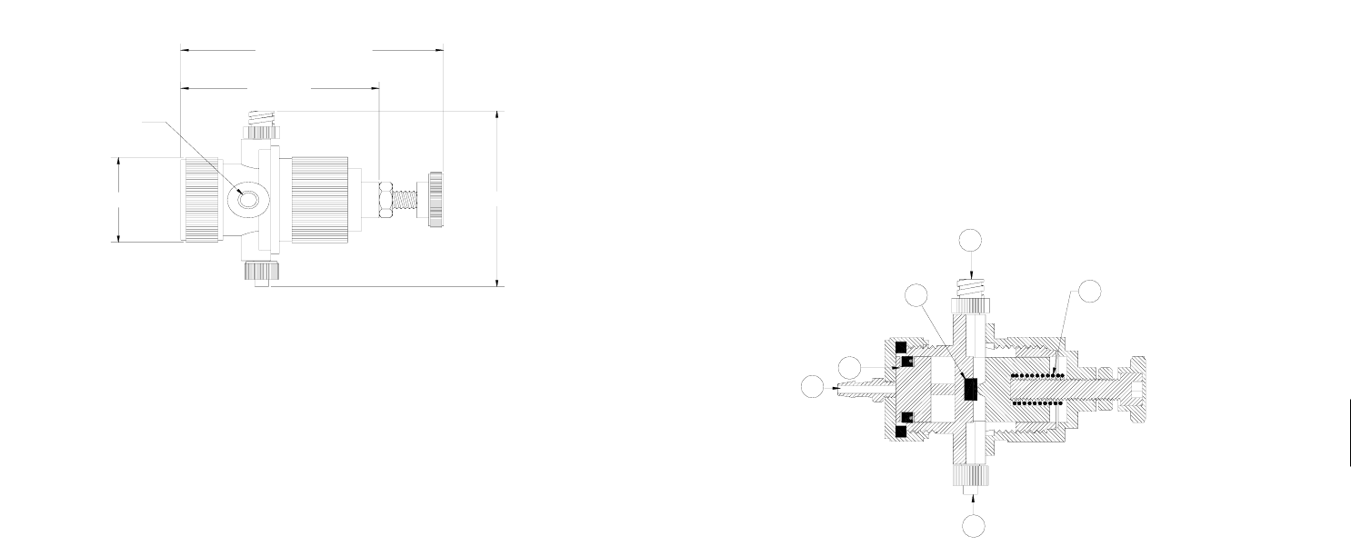
Size: 3.7” (94mm) long; 1.18”(30mm)
diameter
Weight: 0.18 lb (83g)
Fluid inlet port: Female luer lock
Fluid outlet port: Male luer lock
Air inlet port: 10-32 UNF-2B
Maximum fluid pressure: 60 psi (4.1 bars)
Minimum air pressure required: 50 psi (3.4 bars)
Wetted parts: Standard: Polyethylene
Optional: Polypropylene
Operating frequency: Exceeds 400 cycles/min.
Flow rate at 60 psi (water): 2050 ml/min.
Material viscosity range: Up to 45,000 Cps.
Dimensions are in inches (mm)
Figure 1.0
2.35(60)
2.90(74)- 3.7(94)
Ø1.18(30)
2.44(62)
MOUNTING HOLE
1/4-20
4
2. UNPACKING AND INSPECTION
Carefully unpack the valve and examine the items contained in the carton.
These will include:
• Valve Assembly
• Sample Pinch tubes and Needle Kit
• User guide
• Valve Air Hose
Inspect the unit for any damaged which may have occurred in transit. If such
damage has occurred, notify the carrier at once.
Claim for damage must be made by the consignee to the carrier, and should be
reported to the manufacturer.
3. DESCRIPTION
The TS1212 valve is designed to dispense low to medium viscosity material
with precise deposits over a wide range of shot sizes. An internal spring return
makes the valve fully adaptable for use with Techcon Systems time/pressure
controllers. A short opening stroke provides extremely fast, positive shut-off.
An external stroke control adjustment makes it easy for the operator to fine
tune shot sizes.
4. THEORY OF OPERATION
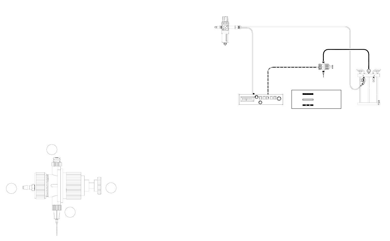
The TS1212 is a normally closed, disposable pinch tube valve. Air pressures
through port (1) pushes the piston assembly (2) away from the seat (3) allowing
fluid to flow from the valve fluid inlet port (4) to the valve fluid outlet port (5).
Relieving the input air pressure allows the spring (6) to return the piston back
to its position to close the fluid path.
Figure 2.0
1
6
5
3
2
4
5
5. SET UP INSTRUCTIONS
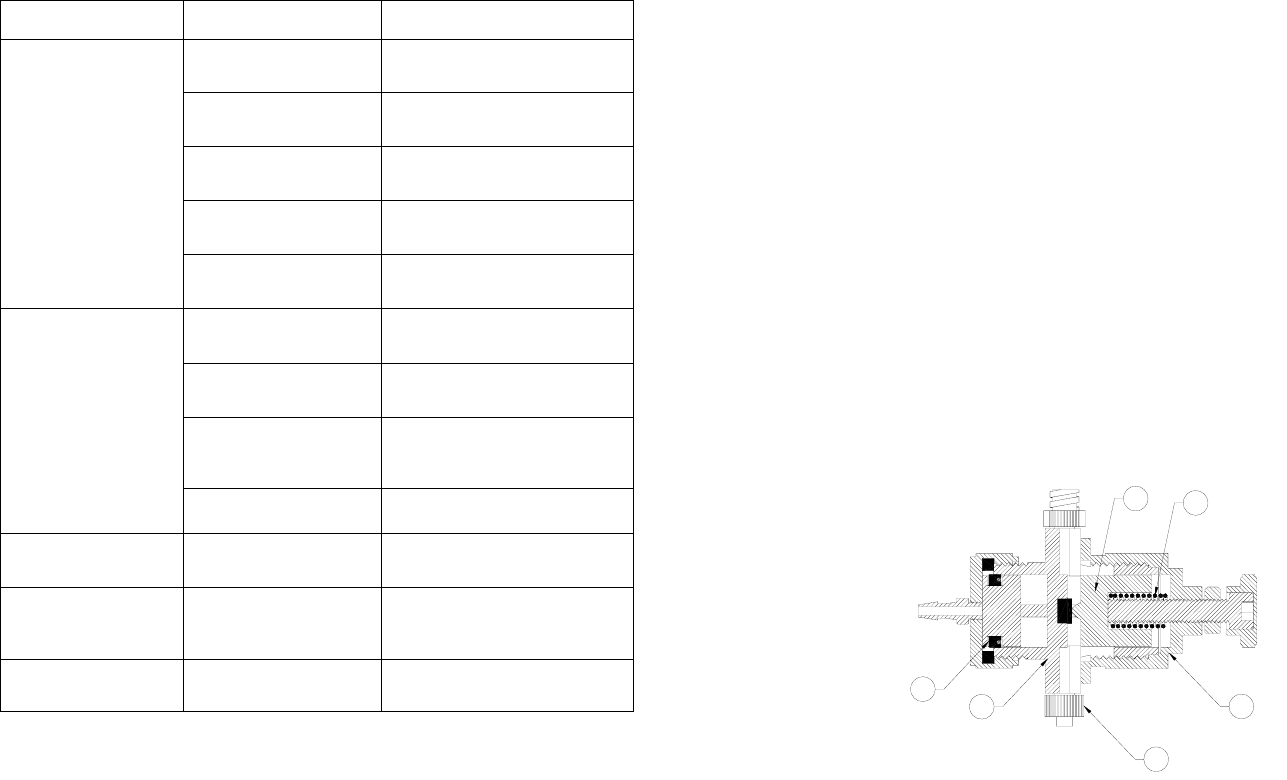
Refer to Figure 3.0
1. Install a new pinch tube in the valve. Following instructions in
Section 6. “Pinch tube replacement” on page 8.
2. If desired, mount the valve to the bracket included.
3. Connect fluid feed line to valve inlet port (1).
4. Install valve actuating air line to air inlet port (2)
5. Connect valve air line to an approved valve controller.
6. Set the fluid reservoir pressure. Do not exceed 60 psi (4.1bars)
7. Make sure all connections are tight
8. Place container under the valve outlet and activate the valve until the
fluid flows steady.
9. Attach appropriate dispense tip to the luer lock outlet fitting (3).
The amount of fluid that flows through the valve is determined by:
• Flow control adjustment- Turn adjustment screw (4)
counterclockwise to increase fluid flow rate and clockwise to
decrease fluid flow rate.
• Length of actuation, set at controller (Valve open time).
• Fluid reservoir pressure.
• Dispensing tip size.
Figure 3.0
1
2
3
4
6
6. TYPICAL SYSTEM SET UP
Figure 4.0
PULSED AIR
CONSTANT AIR
MATERIAL
PLANT AIR MUST BE PROPERLY
FILTERED AND DRY. IF NOT, SPECIFY
A 5-MICRON FILTER REGULATOR.
FLUID FEED SYSTEM
TECHCON SYSTEMS TS5130
CONTROLLER OR EQUIVALENT
TS1212
PINCH TUBE VALVE
7
7. TROUBLE SHOOTING
PROBLEM POSSIBLE CAUSE CORRECTION
Fluid pressure too low Increase fluid pressure
Operating pressure too
low
Increase air pressure to 50 psi
(3.4 bars)
Dispense tip clogged or
damaged
Replaced tip
Fluid cured in pinch
tube
Replace with new tube
No Fluid Flow
The stroke adjustment
closed
Open stroke adjustment
counterclockwise
Fluid pressure
fluctuating
Make sure fluid pressure is
constant
Valve operating
pressure is too low
Increased valve pressure to 50
psi (3.4 bars)
Valve open time is not
consistent
Check to make sure the valve
controller is providing a
consistent output
Inconsistent
Fluid Flow
Air trapped in fluid line Purge valve
Decrease in fluid flow
Pinch tube lose its
flexibility
Replace with new tube
Fluid drools after the
valve closes,
eventually stopping
Air trapped in fluid line Purge valve
Steady drip
Pinch tube is not
installed properly
Re-install tube, follow
instructions
8
8. PINCH TUBE REPLACEMENT
CAUTION: Make sure the fluid pressure is released before disassemble the
valve.
Refer to figure 5.0
1. Release fluid pressure.
2. Disconnect fluid line.
3. Disconnect valve air line.
4. Remove the valve cap (1), the spring (6) and the shut off piston (5)
5. Lift the two ends of the tube (2) out of the grooves of the valve body (3).
6. Hold the pinch tube at the female luer lock fitting and pull it out of the valve
body.
7. Dispose the used pinch tube in an appropriate waste container.
8. Install a new pinch tube by inserting the male fitting of the tube through the
valve body.
9. Snapped the both ends of the pinch tube into the groove of the valve body.
10. Reinstall the shut off piston, the spring and the flange.
Figure 5.0
4
6
2
1
5
3