TS5440.pdf - 第7页
7 7. TROUBLESHOOTING PROBLEM POSSIBLE CAUSE CORRECTION Fluid pressure too low Increase fluid pressure Operating pressure too low Increase air pressure to 70 psi (4.8 bars) Dispense tip clogged or damaged Replaced tip Flu…
6
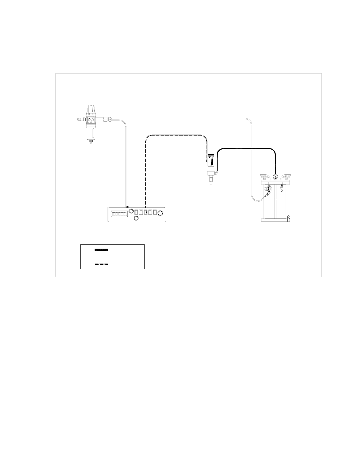
6. TYPICAL SYSTEM SETUP
TECHCON SYSTEMS TS5130
CONTROLLER OR EQUIVALENT
FLUID FEED SYSTEM
TS5440
NEEDLE VALVE
PLANT AIR MUST BE PROPERLY
FILTERED AND DRY. IF NOT, SPECIFY
A 5-MICRON FILTER REGULATOR.
MATERIAL
CONSTANT AIR
PULSED AIR
TS5440
XXXX
Figure 4.0

7
7. TROUBLESHOOTING
PROBLEM POSSIBLE CAUSE CORRECTION
Fluid pressure too low Increase fluid pressure
Operating pressure too low Increase air pressure to 70 psi (4.8 bars)
Dispense tip clogged or damaged Replaced tip
Fluid cured in valve chamber Clean valve thoroughly
No fluid flow
The stroke adjustment closed Open stroke adjustment counterclockwise
Fluid pressure fluctuating Make sure fluid pressure is constant
Valve operating pressure is too
low
Increased valve pressure to 70 psi (4.8
bars)
Valve open time is not consistent
Check to make sure the valve controller
is providing a consistent output
Inconsistent
fluid flow
Air trapped in fluid housing Purge valve
Fluid drools after the valve
closes, eventually stopping
Air trapped in fluid housing Purge valve
Fluid leaks at needle hub Defective dispense needle
Replace needle. Make sure to use TE
series needle only
8
8. MAINTENANCE AND CLEANING:
Tool required: 7/64” hex wrench; 7/16” open-end wrench; Snap ring pliers, O-ring tool.
Normally, purging the valve with appropriate flush material or solvent after use is sufficient for
cleaning. However some material may cause a buildup in the valve chamber, in this case periodic and
thorough cleaning will be required.
NOTE:
• To replace seals, please order seal kit part number: 5440-SEALKIT
• To repair valve, please order valve kit part number: 5440-VALVEKIT
CAUTION: Make sure the fluid pressure is released before disassemble the valve.
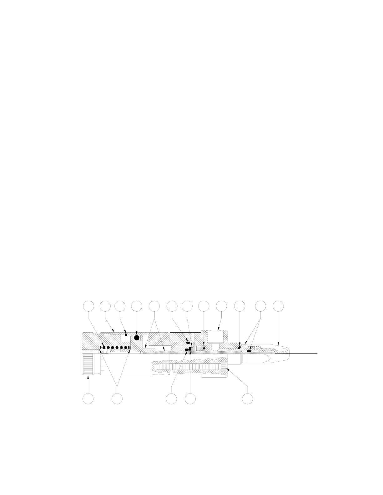
Refer to figure 5.0
1) Release fluid pressure.
2) Disconnect fluid line.
3) Disconnect valve air hose.
4) Unscrew retaining cap (1) and remove the dispense needle.
5) Remove the three mounting screw (17).
6) Pull the fluid housing (4) away from the air cylinder (11).
7) Remove the luer adapter assembly (2) from the fluid housing (4).
8) Clean and inspect the needle assembly (8), luer adapter assembly (2) for wear and
damage. Replace parts as necessary.
9) Replace O-ring (7) if necessary. Make sure to lubricate new O-ring with approved
lubricant.
10) Reinstall the luer adapter assembly (2) to the fluid housing (4).
11) Align the fluid housing (4) to the air cylinder (11) and reinstall the three mounting
screws. (Alternately tighten the screws a little at a tim e until they are secure.
13 14
3465789101112
1
2
1615 17
TS5440
XXXX
Figure 5.0