Cat.No_.AIMEXR_2023.Apr_E.pdf - 第5页
Cat.No.AIMEXR_2023.Apr_E h tt ps : //ww w. f uji. c o.j p /en/ - The contents of this catalog are subject to change without notice. - The information in this catalog is current as of April, 2023. 19 Chausuyama, Y amamach…
040403
Upward warped panelDownward warped panel
Z0
±25µm
+
Placement pressure control
±25µm
+
Placement pressure control
±25µm
+
Placement pressure control
±25µm
+
Placement pressure control
Existing camera
PC01 camera
Intelligent parts sensor (IPS)
LCR check
3D coplanarity check
Placement height adjustment
Pickup deviation
Upside-down part
NormalNormal
ErrorError
Normal
Normal
ErrorError
Z0
Does not place without contacting the panel Does not push on parts too much
Placements can be performed with a high accuracy of ±25 µm
at all times; there are no constraints for the head type or the
part to be placed.Additionally, control the push-in amount
during placement and place with the appropriate pressure.
Offers high accuracy placement as standard
Not affected by changes in the surface
height
The installed IPS system can cater to a wide range of
checks, from part pickup stance to parts remaining on
nozzles, as well as upside-down checks for minimold parts.
It prevents placement defects attributed to packaging,
nozzles, and parts.
Checks for tombstoned, missing, and
upside-down parts
Prevents defects associated with part
properties
The camera equipped with advanced lighting technology,
ensures reliable vision processing of WL-CSPs and other
parts for which the background of parts are likely to be
captured in acquired images. Also, insertion parts are
positioned and inserted accurately by imaging the pin tips.
High accuracy placement for various parts is possible.
Places WL-CSPs with high accuracy
Reliable placement is attained by detecting and adjusting for
the panel warpage and individual part differences using
advanced functions. Maintain productivity and support even
large panels for which it is easy for the warpage to be large
(up to 7 mm).
Placement defects caused by operation errors and defective
parts are prevented by checking the electrical properties of
chip parts with LCR checks and by checking the leads and
bumps on IC parts with coplanarity checks.
(Option)
The throughput in actual production has been
improved by using advanced XY robots and the
latest heads. Even faster placement is achieved
by supporting RH28 heads*.
From high-mix production to mass
production
Improved productivity
Towards zero placement defects
Support any need
RH02
※
RH02
※
RH08RH08
RH20
RH20
0201
(008004")
7 x 7 45 x 38 135 x 120 180 x 35
6.5
14
38.1
( mm )
Double conveyor*Single conveyor
Large panel production Simultaneous production of two models
Optimum operation that matches the production type is possible.
Expand the possible placement area up to the
maximum panel size, 1,068 x 610 mm
Convey the same product type alternately
and produce with two robots efficiently
Convey different product types at the
same time and produce with each robot
Dual lane production with same model
Dual lane production using different models
Uses the same latest heads as the NXTR. By expanding the
range of parts that can be supported, they contribute to line
balancing and flexible production without drops in production
rates even when a different set of parts is used in the next
production.
Placement heads that demonstrate
strong capability in production
With the large capacity part supply units the machine can
hold up to 130 different part types. Shared setups that
utilize the large quantity of loaded parts reduce the
changeover count and operator work loads.
Operation can be optimized in various ways to
suit the part being placed, such as by selecting
stable and optimal operation speeds and
streamlining Z direction strokes in view of the
part height.
Optimal placement actions tailored
to the part
Operations suitable for the product type
Minimize changeover with large capacity
part supply units
Backup pins are automatically allocated only by
setting a picker nozzle in the nozzle station. Product
type changeover can be supported immediately and
production can be restarted in the shortest time.
(Option)
Allocates backup pins automatically
Sub board
Main board
* Under development
* Under development
- Check for dropped parts
- Check for parts remaining
on nozzle
- Check for stuck nozzles
- Check of the part height
- Check for parts presence
Supported part range
Supported part height
*Maximum part sizes include 175 x 50 mm and 167 x 74 mm in addition to the above.
- Multi-level transfer speed
- Shortest Z stroke control
- Program-based positioning
- Auto allocation position check
0605
Maximize machine operation
Sample machine
configurations
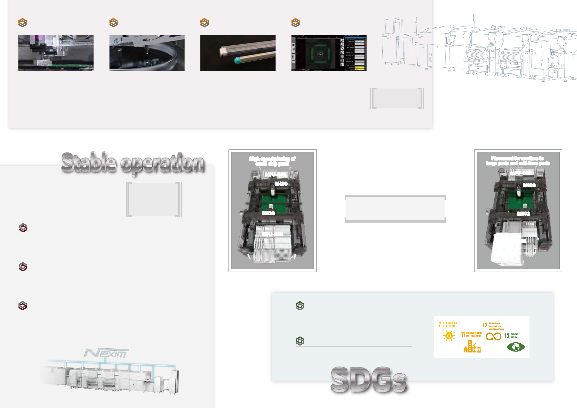
Environmental activities
The machine power consumption has been reduced by 10%* by
using highly efficient motors.
Improved energy efficiency
By automatically saving logs and image data, signs of issues that would cause machine stops
and information that would lead to problem solving is not missed, leading to error prevention
and faster recovery times.
Towards non-stop production
Even if a communication failure with the integrated production system, Nexim occurs,
production can be continued on the line independently. Line stoppages are prevented to
support stable production.*
Enhanced fault tolerance
Maintenance using automation tools for heads, feeders, and nozzles is possible. Reliable
maintenance that does not depend on operator skill greatly reduces the work time. Also,
maintenance guidance that matches the operating conditions makes it possible to perform
maintenance at the optimal timing.
Reliable maintenance
We are reviewing our painting process and efforts are being made
to reduce the environmental impact.
Initiatives for environment conservation
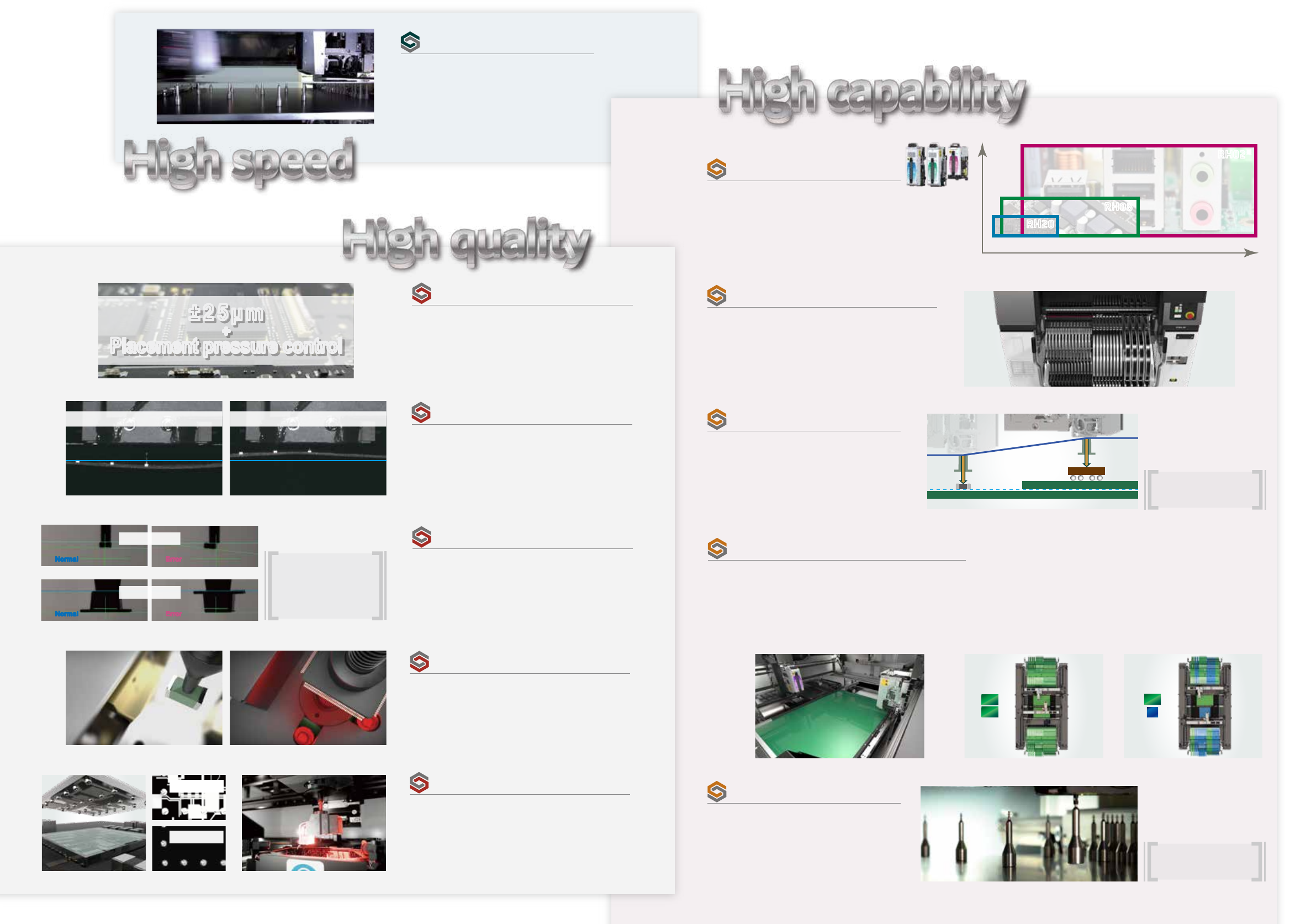
Transfers flux* to bumped parts such as BGAs
and WL-CSPs. High-speed transfer using an
RH20 head is also possible. In addition to flux,
other materials such as solder paste can also
be used.
Transfer flux
RH01 heads* are optimal for large, odd-form,
and heavy parts that are seen in electronic
panels for such as automotive and server
production. Part sizes up to 200 x 150 mm,
part heights up to 38.1 mm, and transportable
weights up to 350 g are supported.
Place large, odd-form, and
heavy parts
With stacked stick feeders, non-stop supply is
possible by stacking stick parts. Also, the
vibratory stick feeder 3 in which up to five types
of parts can be loaded can also be selected.
Supply stick parts
Automatic generation and editing of part data
are possible on the machine. This improves
work efficiency and supports ramping up the
next production.
Edit on the machine and
ramp up production
* Measured under conditions at Fuji.
Production method: Dual lane production
*
Supported panel size: 48 x 48mm to 1,068 x 280mm
Supported part size: 0201 (008004") to 7 x 7 mm, height: 6.5 mm
Production method: Single lane production
Supported panel size: 48 x 48mm to 1,068 x 610mm
Supported part size: 0402 (01005") to 180 x 35 mm*, height: 38.1 mm
RH20RH20
RH20
RH20
MFU-65R
MFU-65R
MFU-65R
MFU-65R
RH08
RH08
RH02
RH02
Tray unit-LTR
Tray unit-LTR
MFU-65R
MFU-65R
High speed placing of
small chip parts
High speed placing of
small chip parts
Placement for medium to
large parts and odd-form parts
Placement for medium to
large parts and odd-form parts
* Maximum part sizes include 135 x 120, 175 x 50, and 167 x 74 mm in addition to the above.
Support any need
- Collects logs automatically
- Saves all images
- On-machine editing
- Multiple language support
- Remote operation
*
- Responds to network issues
*
- Collects logs automatically
- Saves all images
- On-machine editing
- Multiple language support
- Remote operation
*
- Responds to network issues
*
* Under development
* Under development
* Under development
* Under development
* Under development
* Under development
-
Correct vision processing errors
-
Automatic vision data generation
- Place specified sequences*
Cat.No.AIMEXR_2023.Apr_Ehttps://www.fuji.co.jp/en/
- The contents of this catalog are subject to change without notice.
- The information in this catalog is current as of April, 2023.
19 Chausuyama, Yamamachi, Chiryu, Aichi, 472-8686 Japan Tel: +81-566-81-2110
© 2023 FUJI CORPORATION. All Rights Reserved.
MFU-65R
Standard
Sidelight
M
L
1.5L
Tray unit-LTR
2R (Twin robot)
130
48 x 48 mm to 1,068 x 610 mm
±0.025 mm Cpk ≥ 1.00
1,800 kg
3-phase AC200 to 230 V ±10 V (50/60 Hz)
0.4 MPa
250 L/min (ANR)
RH20
41,000 cph
44,500 cph
Single conveyor
RH02
9,000 cph
-
RH08
22,000 cph
-
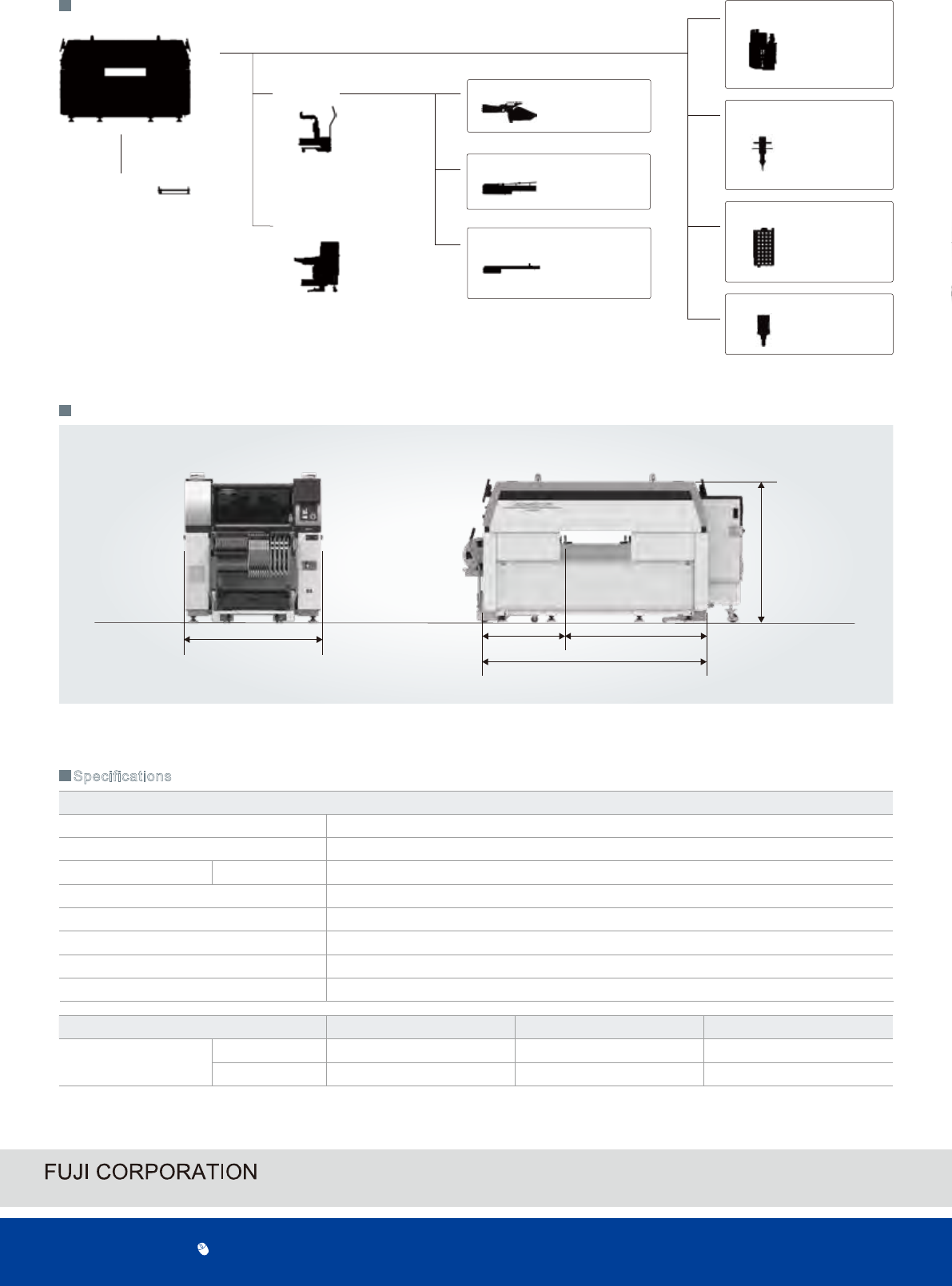
1,460
2,351
1,473
1,481
870
( mm )
External dimensions
System overview
Specifications
Conveyors
Single
Double *
Feeders
Fuji intelligent feeder
(W04 to W104)
Stick feeders
Vibratory type
Stacked type
Reject parts conveyors
φ0.2 to φ20.0
Wide range
(S, M, L)
Mechanical chucks
Picker nozzle
Heads
RH28 *
RH20
RH08
RH02
RH01 *
Nozzles
Nozzle stations
RH28 type *
RH20 type
RH08 type
RH02 / RH01 type
Parts camera
* Under development
Robot quantity
Feeder slot quantity
Panel size
(L×W)
Placing accuracy
*1
Weight
Power source
Air
Air consumption
Heads
Throughput
*1
Normal mode
Productivity priority mode
*1 Under optimum Fuji conditions.