Infinity EX Machine Overview.pdf - 第16页
INFINITY EX MAC HINE OV ERVI EW ADVANT ECH PC ELE CTRONIC S SCHE MATIC 3.16 Technical Reference Manual Chapter Issue 3 Jan 04 AD V ANTECH PC ELECTRONICS SCHEMA TIC The following schematic gi ves an ov ervie w of communic…

INFINITY
EX
MACHINE OVERVIEW
MACHINE PRINT CYCLE
3.14 Technical Reference Manual Chapter Issue 3 Jan 04
parameter menu.
NOTE
If Camera Idle Position is set to Behind Rail the camera is driven from it’s
position in Step 15 to a position behind the rear rail in-line with the board
stop position.
21.On completion of the print stroke the average squeegee pressure is calcu-
lated and if it differs from the set pressure by more than +/- 1Kg a squeegee
pressure error window is displayed. The user is given the option to abort or
continue.
22.If continue is selected, a new squeegee displacement is calculated for the
next print cycle on the particular squeegee.
23.The squeegee mechanism releases full pressure but keeps the squeegee in
contact with the stencil with 0.5kg force.
24.The board count is incremented.
25.The chase clamps are de-energized and the rising table drives down as set by
the separation speed in the board parameter menu until it is clear of the
stencil by the separation distance, at the same time the printing squeegee
drives down to dwell height.
NOTE
If Unload Board Start is set to Separation the board clamps are de-energised
and the front and rear belt motors are driven, while the rising table drives
down to transport height, until the board is detected at the output sensor.
26.The rising table drives down to a height dependent on the under board
clearance setting, at full speed and de-energizes the board clamps.
27.The front and rear belts drive until the board is detected at the output sensor.
28.The cycle counts for the paste dispense and screen cleaner are incremented
and if either has reached the values set by the dispense rate or clean screen
rate then the appropriate cycle is performed.
INFINITY
EX
MACHINE OVERVIEW
ARCOM PC ELECTRONICS SCHEMATIC
Chapter Issue 3 Jan 04 Technical Reference Manual 3.15
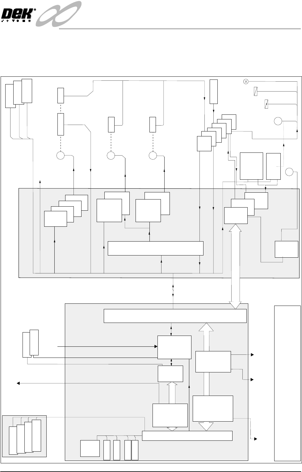
ARCOM PC ELECTRONICS SCHEMATIC
The following schematic gives an overview of communication between the main
electronic/electrical modules of the machine fitted with an Arcom PC.
Host Comms
Infra Red
Link
Remote
Barcode
Reader
Stencil
Barcode
Reader
24v (US)
Servo Motors
24V Stepper Motors :
P.Disp, Rear Squeegee,Rail
24V Stepper Motors :
XF, XR, Y Acts, Fwd Squeegee
Soft E Stop
I/O Breakout Boards
(A to F)
M
M
M
DC Motors
M
Head Lift
Motor
M
Clamps
Pneumatic Valves
Lamps
X2
N
e
x
t
M
o
v
e
X6
X4
Dual
Stepper
X1
M
u
l
t
I
p
l
e
x
e
r
X5
X3
Dual
Stepper
P
r
o
c
e
s
s
o
r
X9
Vision
P. C
Adaptor
X11
PCI Bus
2 Channel
RS 232
Comms
Card
ISA Bus
X4
Fan
HDD
FDD
CDROM
100 Way
Step/Dir - 4,5,6
Step/
Dir-7
Squeegees, Rail, P.Disp - Homes
Mux
Home
Critical Real Time I/Ps, Actuators Home
X13
X12
X11
Multi-
Move
X2
Head
Lift
16 I/Ps, O/Ps
per card
MIU
or
FMI Pod
CAN Bus
NOTE
The CAN Bus forms part of the 100 way connection between
the machine PC and controller enclosures.
Vision
Card
X10
Ethernet
Card
X13
4
Channel
Comms
Card
X7
Keyboard
Monitor
Mouse
Touchscreen
P.S.U
MMI
Camera
Lighting
Machine P.C
Machine Controller
Dmd 0,1,2,3
Servo
Drive
X7
X8
X10
X9
Pressure
Temp
Humidity
Encoder
Home
Home
Home
Sensors
HTC
Controller
INFINITY
EX
MACHINE OVERVIEW
ADVANTECH PC ELECTRONICS SCHEMATIC
3.16 Technical Reference Manual Chapter Issue 3 Jan 04
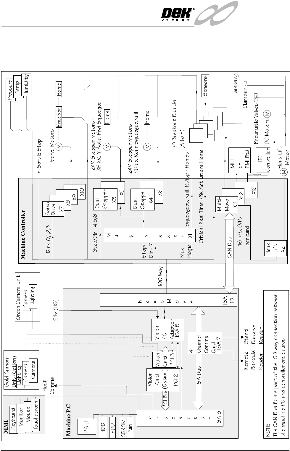
ADVANTECH PC ELECTRONICS SCHEMATIC
The following schematic gives an overview of communication between the main
electronic/electrical modules of the machine fitted with an Advantech PC.