00900170-01_ID_OIS_SIS_16.0_R18-2_EN_DE.pdf - 第22页
ASM OIS/SIS Datab ases 16.0 (R18 -2) / Interf ace Description 11/2018 Edition 22 STATE_PCB_END 2 Production has been ended (Conveyor 1) STATE_PCB_END2 32 Production has been ended (Conveyor 2) STATE_BREAK_BEGIN 3 Machine…
ASM OIS/SIS Databases 16.0 (R18-2) / Interface Description 11/2018 Edition
21
4.5.1.14 EVENTTEXT Table
EVENTTEXT
OIS name
Data type
Byte
I
P
Event number
sEvent
smallint
2
Event name
strName
nvarchar(32)
64
4.5.1.15 STATETRANSITION Table
STATETRANSITION
OIS name
Data type
Byte
CI
I
P
Identification number of the station
(reference to STATION table)
lId
int
4
✓
Conveyor belt 1 / 2
ucConveyor
tinyint
1
Processing area 1 / 2
ucProcessingArea
tinyint
1
State based on events
sState
smallint
2
Date/time at which this event occurred. Local
station time
dtTime
datetime
8
✓
Time when the data is written. Local server time
dtCreated
datetime
8
✓
Event number
sEvent
smallint
2
Processing mode
usProcessingMode
tinyint
1
Sequence ID (internal use)
lIdSequence
bigint
8
State history (internal use)
IHistory
int
4
Definition of ucConveyor
The current implementation is processing area specific, i.e. one state machine is available for each
processing area. Future improvements may use a state machine for each processing area and
each conveyor. As long as this improvement is not implemented, the ucConveyor is always set to
"0".
Definition of ucProcessingMode
The ucProcessingMode indicates whether the "Alternating" or "I-Placement" mode was used to
process the board.
Possible values of ucProcessingMode:
0:
Undefined
1:
Alternating mode
2:
I-Placement mode
Definition of sState values
The following table contains the state definitions as well as a short description of the state
semantics.
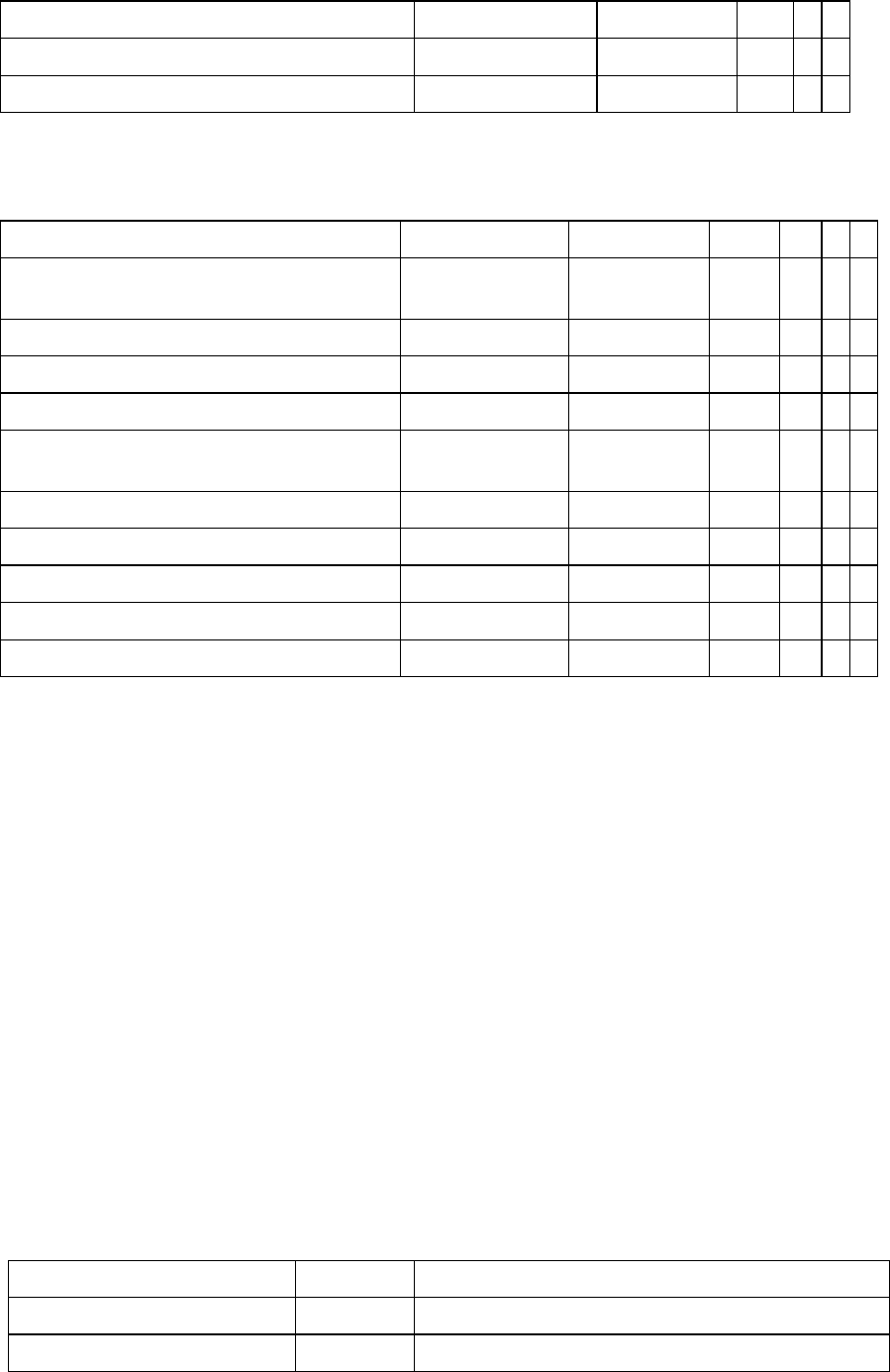
State
Value
Description
STATE_PCB_BEGIN
1
Production has been started (Conveyor 1)
STATE_PCB_BEGIN2
31
Production has been started (Conveyor 2)

ASM OIS/SIS Databases 16.0 (R18-2) / Interface Description 11/2018 Edition
22
STATE_PCB_END
2
Production has been ended (Conveyor 1)
STATE_PCB_END2
32
Production has been ended (Conveyor 2)
STATE_BREAK_BEGIN
3
Machine reported break mode s
STATE_EMERGENCY_STOP
4
Emergency stop has been pressed
STATE_AIR
5
Not enough air
STATE_STOP
6
Machine has been stopped
STATE_WAIT_PCB_IN
9
Machine runs empty. No board is detected in the input
section.
STATE_WAIT_PCB_INSIDE
10
Board is transported
STATE_WAIT_PCB_OUT
11
Board cannot be moved out of the placement area.
Placement cannot be continued.
STATE_WAIT_DATA
12
Machine is waiting for data
STATE_FIDUCIAL_ERROR
14
A fiducial error has been reported from the station
STATE_TRACK_ERROR
15
A track error has been reported from the station
STATE_MACHINE_ERROR
16
A fatal machine error occurred
STATE_TRANSPORT_ERROR
17
A transport error occurred
STATE_BARCODE_ERROR
18
A barcode error has been reported from the station
STATE_HEAD_STEP
20
Machine entered the head step mode
STATE_KEY_SLOW
21
Machine entered the key slow mode
STATE_VISION
22
Machine entered the Vision mode
STATE_FUNCTION
23
Machine is in "Maintenance" mode
STATE_INIT
24
Machine starts up or still needs data or a successful
reference run for automatic production.
STATE_HOLIDAY
25
Operator entered the works holiday mode
STATE_MAINTENANCE
26
Operator entered the preventive maintenance mode
STATE_SETUP
27
Operator entered the setup mode
STATE_DOWN_PLAN
28
Operator entered the scheduled downtime mode
STATE_DOWN_ILL
29
Operator entered the unscheduled downtime mode
STATE_PROTOTYPE
30
Operator entered the load product mode
STATE_STAND_ALONE_BEGIN
49
Stand alone mode has been entered
STATE_STAND_ALONE_END
50
Stand alone mode has been left
STATE_DISPENSING
70
Printer entered the dispensing mode
STATE_KNEADING
71
Printer entered the kneading mode
STATE_PRINTING
72
Printer entered the printing mode
STATE_INSPECTION
73
Printer entered the inspection mode
STATE_CLEANING
74
Printer entered the cleaning mode

ASM OIS/SIS Databases 16.0 (R18-2) / Interface Description 11/2018 Edition
23
4.5.1.16 GantryState Table
The GantryState table reflects gantry state changes. The gantry states have been added to extend
the state transitions stored in STATETRANSITION table.
GantryState
OIS name
Data type
Byte
CI
I
P
Identification number of the station
(reference to STATION table))
lId
int
4
Number of gantry within the processing area
ucNumber
tinyint
1
Processing area 1 / 2
ucProcessingArea
tinyint
1
Gantry state value
sState
smallint
2
Error reason (is sState in Error state)
sErrorReason
smallint
2
BoardNumber of the board that has been
processed when the state change occurred.
lBoardNumber
int
4
Unique sequence id of the entry
lIdSequence
bigint
8
Date/time at which this event occurred.
Station time
dtTime
datetime
8
Definition of sState values
0:
Undefined
1:
Idle
2:
Interrupted
3:
Processing
4.5.1.17 PlocState Table
The PlocState table contains state changes related to the processing location. These states act as
extensions of the state changes related to the processing area that are stored in the
STATETRANSITION table.
PlocState
OIS name
Data type
Byte
CI
I
P
Identification number of the station
(reference to STATION table)
lId
int
4
Conveyor belt 1 → right / 2 → left
ucConveyor
tinyint
1
Processing area 1 / 2
ucProcessingArea
tinyint
1
PlocState state value
sState
smallint
2
Unique sequence id of the entry
lIdSequence
bigint
8
Date/time at which this event occurred.
Station time
dtTime
datetime
8
The definitions of the PlocStates (sState) are the same as those described in section 4.5.1.15.