ThermoFlex-Manual.pdf - 第46页
Section 3 3-8 ThermoFlex Thermo Scientific Hard Wire Installation F or per sonal safety and equipment reliability , only a qualied technician should perfor m the following procedur e. Note The technician is responsible…

Section 3
ThermoFlex 3-7
Thermo Scientific
** Chillers selected for 230 VAC operation have a range of -10% to +7%. Refer to Appendix A for
country specific ratings.
For installation information on global voltage chillers refer to Appendix B.
electrical requirements.
ThermoFlex15000/20000
(Air-cooled)
Voltage ±10% Frequency Phase MCA MOPD Line Cord
Plug
400 VAC P 3 Pump 50 Hz 3Ø 16.2 30 Hard wire
400 VAC P 5 Pump 50 Hz 3Ø 18.4 30 Hard wire
460 VAC P 3 Pump 60 Hz 3Ø 16.2 30 Hard wire
460 VAC P 5 Pump 60 Hz 3Ø 18.4 30 Hard wire
ThermoFlex15000/20000
(Water-cooled)
Voltage ±10% Frequency Phase MCA MOPD Line Cord
Plug
400 VAC P 3 Pump 50 Hz 3Ø 14.5 25 Hard wire
400 VAC P 5 Pump 50 Hz 3Ø 16.7 30 Hard wire
460 VAC P 3 Pump 60 Hz 3Ø 14.5 25 Hard wire
460 VAC P 5 Pump 60 Hz 3Ø 16.7 30 Hard wire
ThermoFlex24000
(Air-cooled)
Voltage ±10% Frequency Phase MCA MOPD Line Cord
Plug
400 VAC P 3 Pump 50 Hz 3Ø 20.1 35 Hard wire
400 VAC P 5 Pump 50 Hz 3Ø 22.3 40 Hard wire
460 VAC P 3 Pump 60 Hz 3Ø 20.1 35 Hard wire
460 VAC P 5 Pump 60 Hz 3Ø 22.3 40 Hard wire
ThermoFlex24000
(Water-cooled)
Voltage ±10% Frequency Phase MCA MOPD Line Cord
Plug
400 VAC P 3 Pump 50 Hz 3Ø 18.8 35 Hard wire
400 VAC P 5 Pump 50 Hz 3Ø 21.0 35 Hard wire
460 VAC P 3 Pump 60 Hz 3Ø 18.8 35 Hard wire
460 VAC P 5 Pump 60 Hz 3Ø 21.0 35 Hard wire
MCA = Minimum Current Ampacity
MOPD = Maximum Overcurrent Protective Device
Values reflect those on the nameplate located on the rear of the chiller .
Section 3
3-8 ThermoFlex
Thermo Scientific
Hard Wire Installation
For personal safety and equipment reliability, only a qualied
technician should perform the following procedure.
Note The technician is responsible for installing circuit protection for
incoming power. Before wiring consult the nameplate on the rear of the
chiller. Ensure installation is in accordance with the National Electrical Code
and any other applicable country and local codes.
For ThermoFlex900 through 10000 chillers
Remove the six screws securing the electrical box cover to the chiller.•
Remove the double knock out ( •
7
/
8
" and 1
3
/
32
").
Insert the cable through the hole.•
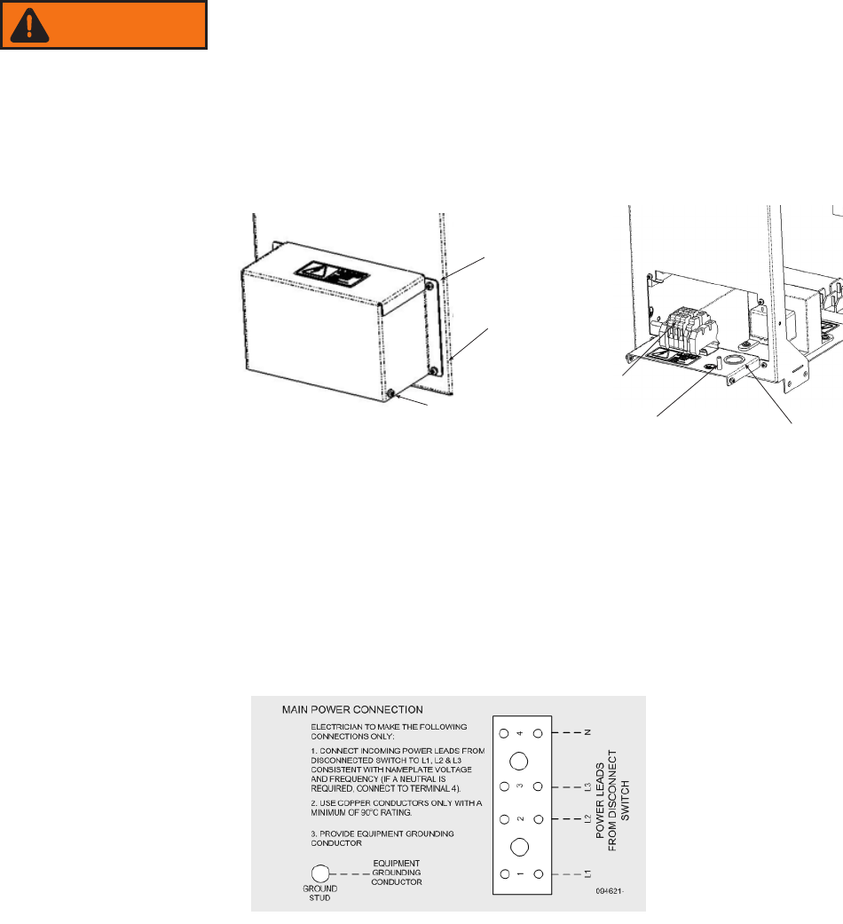
Refertothelabelintheelectricalboxtocongureyourchiller,seeFigure3-3.•
Secure the cable's ground wire to the ground stud.•
Reinstall the cover.•
For ThermoFlex15000, 20000 and 24000 chillers
Removethevescrewssecuringtheelectricalpaneltothechiller.•
Refertothelabelintheelectricalboxtocongureyourchiller,seeFigure3-3.•
Secure the cable's ground wire to the ground stud.•
Reinstall the panel..•
(2)
Terminal Block
Ground Stud
Knock Out
(2)
(2)
Figure 3-2 Electrical Box
Figure 3-3 Sample Label
WARNING
Section 3
ThermoFlex 3-9
Thermo Scientific
Plumbing
Requirements
Ensure that all shipping plugs are removed before installation.
Never connect the process uid lines to your facility water supply or
any pressurized liquid source.
To prevent damage to the chiller's plate exchanger, centrifugal pumps
require a 4.0 gpm (15.1 lpm) minimum ow rate.
P 1 and P 2 pumps are capable of producing 185 psig. Ensure your
plumbing is rated to withstand this pressure at your operating
temperature. An external pressure relief valve is available, see Section 5.
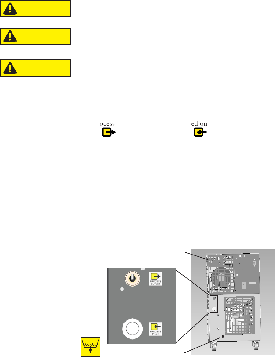
Note Ensure your plumbing installation develops a back pressure to the
labeled
(PROCESS OUTLET) and ().
Process Fluid Connections (FNPT)
Outlet
ThermoFlex900 - 10000 P 1 P 2 T 0 T 1 1/2" cast bronze
ThermoFlex3500 - 5000 P 3 P 4 3/4" cast bronze
ThermoFlex7500 - 24000 P 3 P 5 T 5 1" wrought copper
Supplied Adapters
P 1 P 2 T 0 T 1 1/2" x 3/8'' Polyethylene and 1/2" x 1/2" Nylon
P 3 P 4 3/4 MPT x 1/2 barb PVC
P 3 P 5 T 5 1" MPT x 1" Barb PVC and 1" MPT x 3/4" Barb PVC
CAUTION
CAUTION
CAUTION
1/4" Female NPT Riton Reservoir
Drain Plug
See Section 2 for the specific
locations on your chiller.
Figure 3-4 Typical Plumbing Connections (1 of 2)
DRAIN
Stainless steel outlet connection for chillers
with P 1/P 2 pumps and a flow transducer