Printer 710_810 v8 Machined C Chase Module.pdf
MACHI NED C CHAS E MODUL E OVERVIEW Chapter Issue 1 Nov 05 Technical Reference Manual 14.1 CHAPTER 14 MACHI NED C CHASE MODULE OVERVIEW Item Descrip tion Item Description 1 Machi ned Cha se 6 Front Ju stified Im age Scal…
MACHINED C CHASE MODULE
OVERVIEW
Chapter Issue 1 Nov 05 Technical Reference Manual 14.1
CHAPTER 14 MACHINED C CHASE MODULE
OVERVIEW
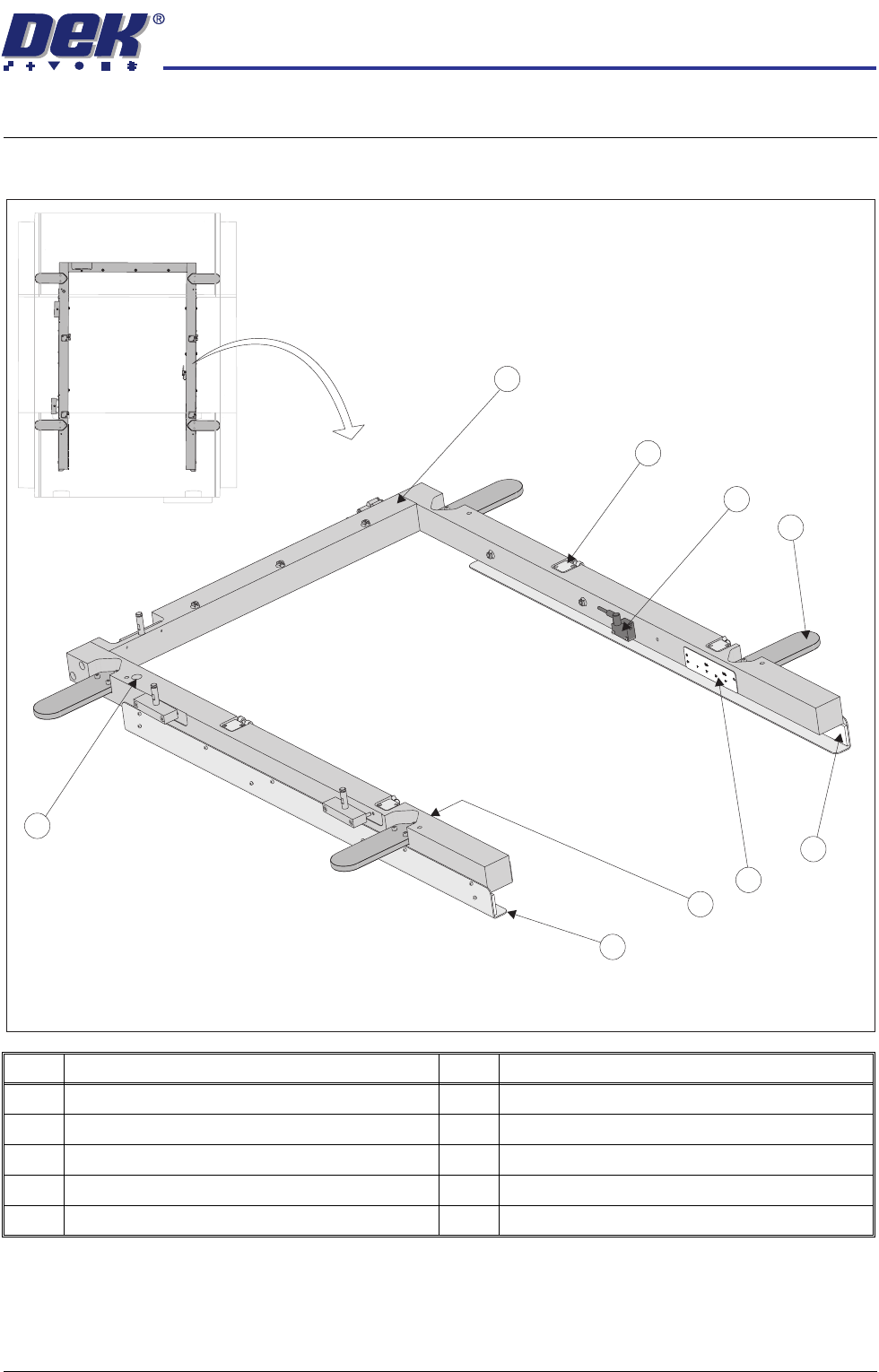
Item Description Item Description
1 Machined Chase 6 Front Justified Image Scale
2 Pneumatic Screen Clamps (4 positions) 7 Centre Justified Image Scale
3 Screen Position Sensor 8 Stencil Support Plate (2 positions)
4 Roller Counter Plate (4 positions) 9 Mechanical Stop Access Hole
5 Stencil Guide Strip (2 positions)
1
2
3
5
6
7
4
Chase Assembly (Isometric View)
8
9

MACHINED C CHASE MODULE
OVERVIEW
14.2 Technical Reference Manual Chapter Issue 1 Nov 05
There are three methods for housing and securing the screen in the machine,
the first is a fixed width system and is described in this chapter, the second is
also a fixed width system and is described in the Cast C Chase chapter, the third
is an adjustable width system and is described in the Adjustable Screen Mount
(ASM) chapter.
The machined C chase module provides a receptacle for the screen, which is
clamped in the correct position for printing operations. The standard screen is
29 inches square, a stencil frame adaptor can also be used to accommodate
smaller screen sizes. The screen image can be front or centre justified.
The screen is loaded from the front of the machine and slid into the machine
along the stencil support plates. The spring loaded right hand stencil guide strip
aligns the screen with the fixed left hand stencil guide strip, ensuring that the
screen is held in the correct location for printing.
A front justified image scale on the right and a centre justified image scale on
the left, allow for the correct positioning of the screen within the chase. A
mechanical stop on the chase allows for the correct positioning of 29 inches
square, front justified stencils.
The chase is a floating assembly mounted on a bearing set. The screen is
clamped in the chase using pneumatic cylinders that clamp the screen to the
stencil support plates.
The chase is positioned to align the screen to the correct printing position.
During printing, the chase is pneumatically clamped to the left and right print-
head assemblies, to maintain the aligned position, by the screen alignment
module (for further details refer to the Screen Alignment Module chapter in this
manual).
A screen position sensor is used to detect the presence of a screen in the chase.
MACHINED C CHASE MODULE
ELECTRICAL SCHEMATIC
Chapter Issue 1 Nov 05 Technical Reference Manual 14.3
ELECTRICAL SCHEMATIC
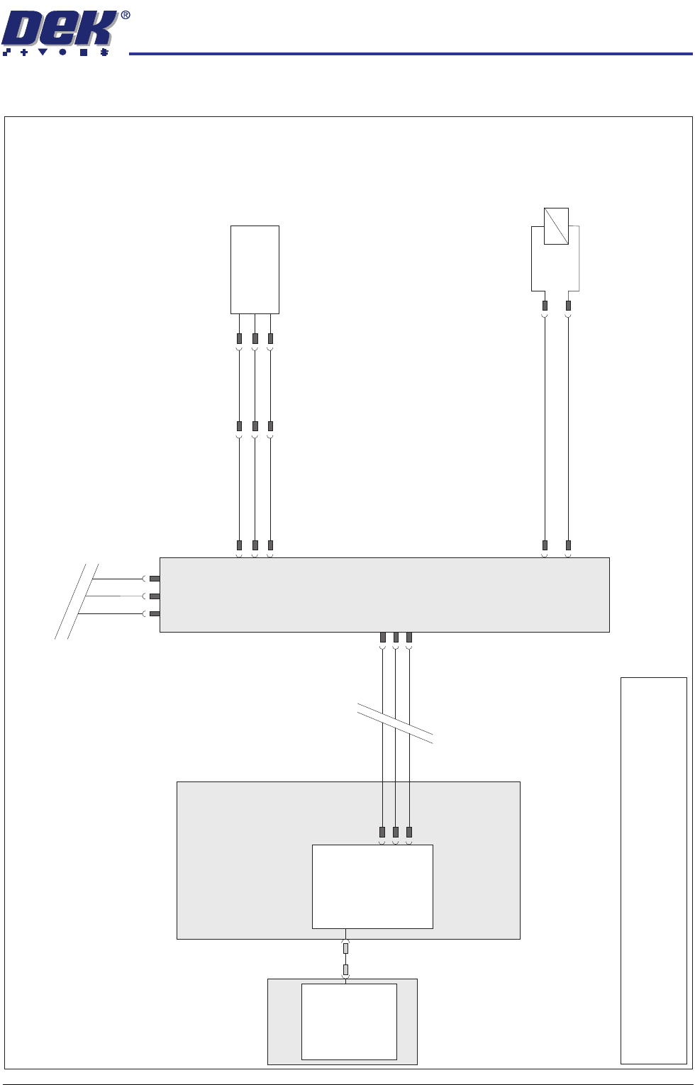
M36 Machine
Control Enclosure
PC
USB
Motherboard
NextMove ES
(I/O Node 1)
1
2
4
CAN_H
CAN_L
CAN GND
M36PL35
CAN In
CAN Bus
Main
Machine
I/O Node 2
N2SK2
7
2
3
CAN
Out
N2SK3
7
2
3
16SK07
Screen
Clamps
16SOL07
DIG OUT 8
N2PL4
0V
2
15
+
-
N2PL10
1
2
3
13PL01
1
2
3
DIG IN 3
Screen Position
Sensor
13SE25
+12V
Sig
0V
13SK25
1
2
3
NOTE
The breaks in the CAN Bus chain reflect that additional I/O Nodes
may be fitted, refer to Machine Control chapter for the complete
CAN Bus chain.