182049 Viking Installation Manual.pdf - 第62页
semi automatic POWER UP SEQUENCE MACHINE POW ER UP SEQUEN CE 6.10 Instal lation Manual Chapter Issue 1 Oct 02 21. At the Menu Bar select Incr . or Decr . to increase or decr ease the Contact Position set hei ght by 0.5mm…

semi automatic
POWER UP SEQUENCE
MACHINE POWER UP SEQUENCE
Chapter Issue 1 Oct 02 Installation Manual 6.9
Paste Dispenser Function Check (if fitted)
ProFlow Contact
Position Setup
For machines using ProFlow only, set up the contact height position as follows:
1. In Module Diagnostics Page select Rising Table.
2. Select Home Rising Table. Select Run Diagnost. Select Exit.
3. In Module Diagnostics Page select Camera Axes.
4. Select Home Camera X Axis. Select Run Diagnost.
5. Select Home Camera Y Axis. Select Run Diagnost. Select Exit.
6. In the Module Diagnostics Page select ProFlow.
7. Select Home ProFlow. Select Run Diagnost. Select Exit.
8. In the Module Diagnostics Page select Print Carriage.
9. Select Home Print Carriage. Select Run Diagnost.
10. Select Drive Carriage Using Jog Buttons. Using the jog buttons drive the
Print Carriage to the mid position of the stencil.
11. Load a stencil with an off centre image.
12. At the MMI select Exit to return to Module Diagnostics Page.
13. In the Module Diagnostics Page select ProFlow. Select Adjust on the
Menu Bar.
14. In the ProFlow Adjust Parameters select PFLOW CONTACT POS.
15. At the Menu Bar select Incr. or Decr. to set the Contact Position to 5.5mm.
16. Fit an empty transfer head to the ProFlow pressure mechanism. Remove
the cover.
NOTE
Ensure wipers and skis are fitted to the transfer head.
17. Position a 0.1mm shim on the stencil under the transfer head.
18. In the Module Diagnostics Page select Drive System to Contact Height.
Select Run Diagnost.
NOTE
Correct contact height is when the shim is just held between the transfer
head wipers and stencil. At this position it is not possible to slide the shim
sideways past the transfer head skis. If correct contact height is not yet
achieved, carry out the following steps:
19. Select Adjust on the Menu Bar.
20. In the ProFlow Adjust Parameters select PFLOW CONTACT POS.
Detail Accept
Set the paste cartridge empty sensor to operate correctly using
the customers solder paste.

semi automatic
POWER UP SEQUENCE
MACHINE POWER UP SEQUENCE
6.10 Installation Manual Chapter Issue 1 Oct 02
21. At the Menu Bar select Incr. or Decr. to increase or decrease the Contact
Position set height by 0.5mm (eg 5.0mm or 6.0mm). Select Exit.
NOTE
Normally the contact position is between the range of 4mm - 8mm (nomi-
nally 6mm).
22. In the Module Diagnostics Page select Drive System to Contact Height.
Select Run Diagnost.
23. Check if contact height is correct, (as detailed in NOTE above). If adjust-
ment is still required repeat Steps 19 to 22 varying the set position until
correct height is achieved.
24. On completion of contact height set up select Home ProFlow on Module
Diagnostics Page. Select Run Diagnost.
25. Remove shim.
semi automatic
MACHINE PERFORMANCE
MACHINE CAPABILITY
Chapter Issue 1 Oct 01 Installation Manual 7.1
CHAPTER 7 MACHINE PERFORMANCE
MACHINE CAPABILITY
Load the product file named 265test1 from the hard disk and with a DEK
alignment board loaded ensure that the following parameters are correct:
• Screen - Calibration/Dry Align
• Squeegee - Length to suit board /ProFlow - Empty Transfer Head
• Front & Rear Print Speed - 25mm/sec (squeegees) / 70mm/sec (ProFlow)
• Front & Rear Pressure - 5kg (squeegees) / 3kg (ProFlow)
• ProFlow Paste Pressure - 2.2 bar
• Separation Speed - 1mm/sec.
• Under Board Clearance - 20mm
• Paste Dispense - 0
• Under Screen Rate - 0
• SPC Data Output Rate - Every Cycle
• SPC Data Mode - Disk
• SPC Format - Windows
• SPC Align Inspect Mode - Post Print
Use nine magnetic tooling pins to fully support the board, apply small amount
of paste or suitable lubricant (enough to lubricate squeegees). Using SPC
Mode, record >100 full machine cycles and setup QC-Cal program as follows:
1. Open Explorer from the Windows Start button. If squeegees are fitted
ensure the filter files sqy1.qcf and sqy2.qcf are present in the directory
structure C:\Prolink\QcCalc\Filters.
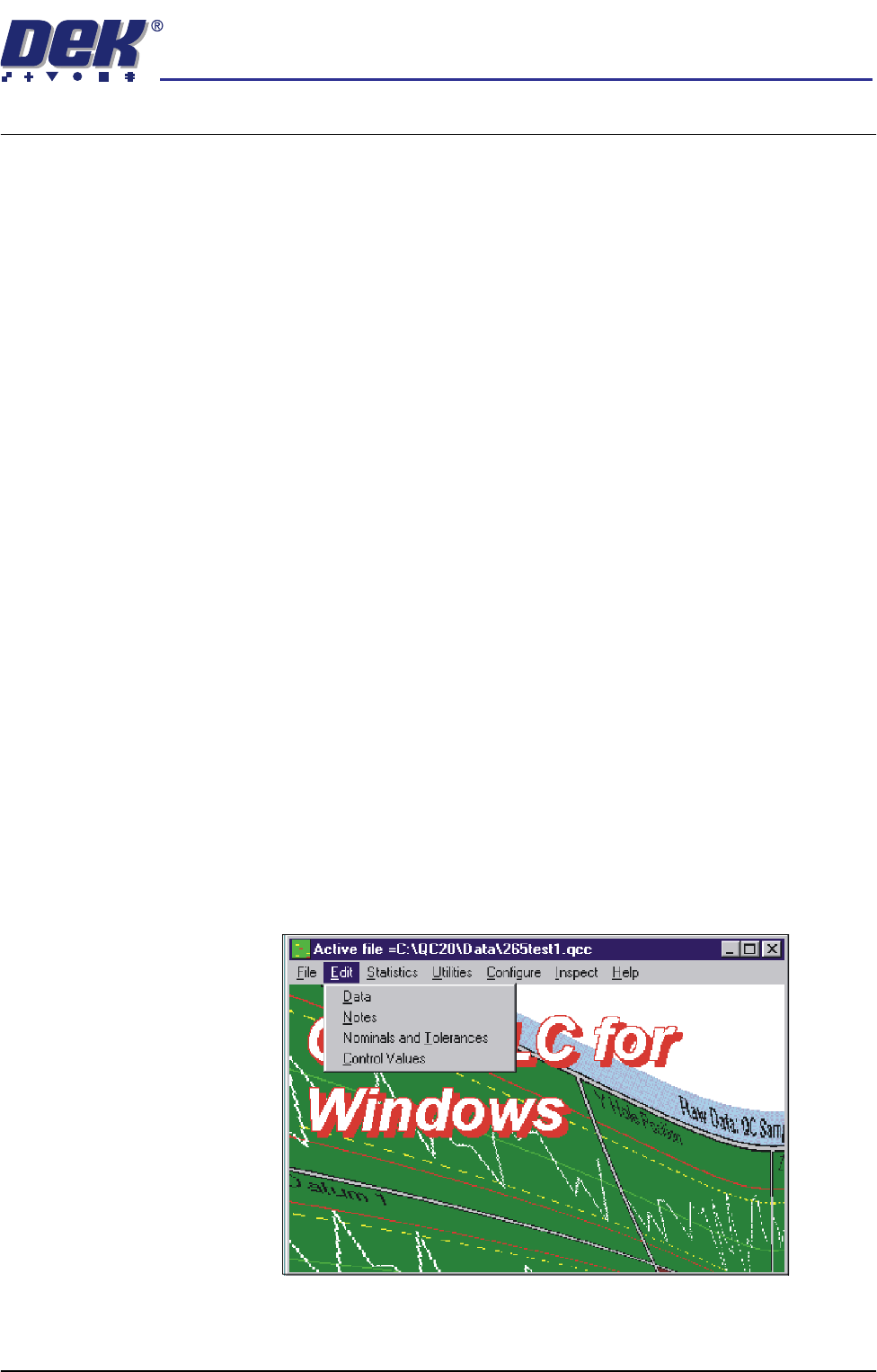
2. Start the QC-Cal program.
3. Select Edit, Data.