PS288_OwnersMnl_PriorTo2009.pdf - 第84页
Operation • Administrato r Functions 3—24 PS288 Owner’s Manual •C l i c k Ye s to overwrite previous values. Figur e 3-29— Rotation value a t V ision •C l i c k P1 . The gantry moves the PNP head to Program mer 1 locatio…
Operation • Administrator Functions
PS288 Owner’s Manual 3—23
• Press <Enter>.
•Click Save.
•Click Ye s to overwrite previous values.
• Repeat for ALL input media (tray, tape and tube).
NOTE: The R-axis rotation value at ALL input media must be
0.000.
3b) Set R-axis rotation at Vision and socket:
•Click Vis to move the PNP head to the vision location.
• Click the Rotation icon.
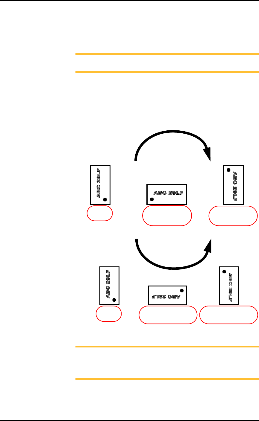
• Enter the R-axis rotation value required to rotate the device so that
pin 1 on the device matches pin 1 on the socket. See Figure 3-28:
Figure 3-28—R-axis values for rotation
NOTE: For example, if a device must be rotated a quarter turn in
the clockwise direction as it goes from the input media to the socket,
set the R-axis at the socket to -0.250. In this example, 0.250 is
entered. See Figure 3-29.
• Press <Enter>.
•Click Save.
R =
-
0.250
(quarter turn clockwise
with respect to Origin)
R =
-
0.500
(half turn clockwise
with respect to Origin)
R = 0.000
(at Origin)
CLOCKWISE
R = 0.250
(quarter turn counterclockwise
with respect to Origin)
R = 0.000
(at Origin)
R =
0.500
(half turn counterclockwise
with respect to Origin)
COUNTERCLOCKWISE
Operation • Administrator Functions
3—24 PS288 Owner’s Manual
•Click Ye s to overwrite previous values.
Figure 3-29— Rotation value at Vision
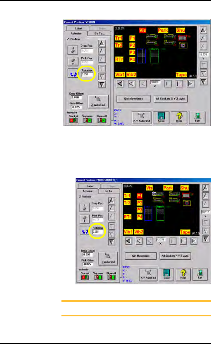
•Click P1. The gantry moves the PNP head to Programmer 1 location.
• Click the Rotation icon.
• Enter the same R-axis rotation value entered at the Vision location.
• Press <Enter>.
•Click Save.
•Click Ye s to overwrite previous values.
Figure 3-30—Rotation value at P1
NOTE: The R-axis value at ALL programmer locations and the
Vision location must be the same.
• Repeat for ALL programmer locations.
Operation • Administrator Functions
PS288 Owner’s Manual 3—25
4. Move device to the Vision system—
4a) Pick up the device by bringing the cursor over the programmer label
and right-clicking the touchpad.
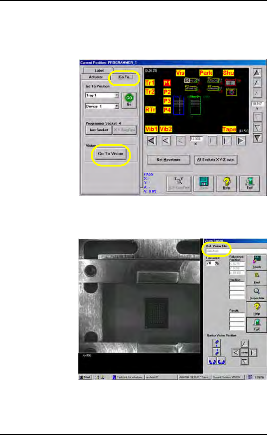
4b) On the Gantry window, select the Go To... tab.
4c) Click Go To Vision. The device moves to the Vision system.
Figure 3-31—On Go To tab, click Go to Vision
5. Verify correct file—
On the Vision System window, note that the name of the reference
vision file for this Job is displayed.
Figure 3-32—Reference vision file name