00191498-01.pdf - 第22页
Stromversorgung Umrüstanleitung S-20/S-23 HM/F4/F5 11 Anhang (Stromlaufpläne) Ausgabe 09/99 22 11 11
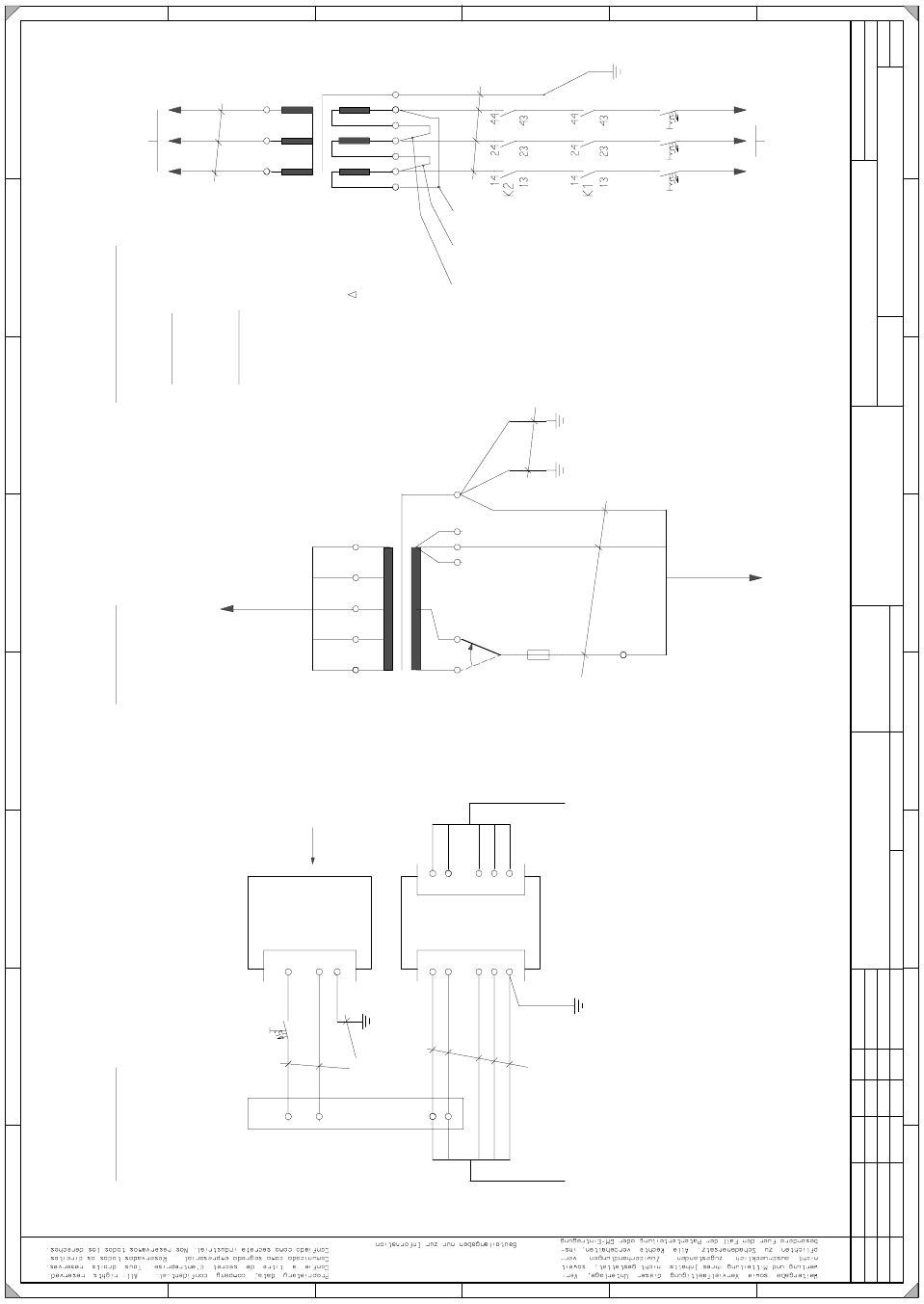
Umrüstanleitung S-20/S-23 HM/F4/F5 Stromversorgung
Ausgabe 09/99
21
=
D
atum
G
ep
r.
N
o
rm
B
ea
rb
.
B
latt
U
rsp
r.
E
rs. f.
E
rs. d
.
N
am
e
D
atum
A
e
n
de
ru
ng
Z
usta
nd
S
IE
M
E
N
S
A
G
B
l
.
+
D
8
S
M
D
-B
estu
ecka
u
to
m
a
t S
IP
L
A
C
E
8
0 S
2
0
/ S
2
3 / F
4 / F
5
B
fu
er S
IP
LA
C
E
80 S
2
0 / S
23 / F
4 / F
5
F
3
A
E
3
2
D
C
B
steckdos
e
L
N
P
E
C
6A
2
,5m
m
2
2
,5m
m
2
1
,5
m
m
2
1
,5
m
m
2
5
C
1
4
2
5
4
6
A
7
F
1
8
7
E
6
zu
m
sw
br
sw
bl
gn
g
e
N
et
zfilter
sw
b
l
b
r
b
l
gn
g
e
N
e
ztstecke
r
zum
g
ng
e
S
ervice-
S
tecka
da
pter
b
r
1
N
N
1
N
L1
L2
L3
P
E
N
L1
L2
L3
P
E
C
6A
2
1
6
5
4
3
K
le
b
esch
ild
:
6
,3
A
T
/
11
0
V
gn
ge
T
rafo B
E
-T
isch
B
ereich d):
S
trom
verso
rgung W
P
W
B
ereich e):
S
ervicestec
kdose
B
ereich c):
X
1
2
3
1
4
Z
1
A
1
F
1
2
1
Y
5
0
1
-W
1
Y
5
0
1
-W
2
.9
1
7
X
21
6
g
nge
H
au
ptschalte
r
6
,3
0A
T
br
bl
gnge
zum
N
etzanschluss
110
V
/ 60H
z
T
rafo
P
ro
zesso
rp
la
tine
B
E
-T
isch
zur
1
0
9
8
7
6
5
4
3
2
1
1
2
1
1
P
in
5 -->
P
in
4
A
b
de
ck
un
g
M
a
sse
T
isch
M
asse
1
,5m
m
2
F
1
65
65
2
0
8V
/ 60H
z
N
etzeinspe
isung
zur
g
nge
sw
s
w
sw
rt
rt
rt
G
le
ichrichtern
zu den
G
1/G
2
D
reie
ck-S
cha
ltu
ng
2
,5
m
m
2
T
1
Y
5
4
5
-W
1
Y
558-W
1
5
4
3
2
1
F
1
U
m
ruestsatz 11
0/208V
2
30
V
/4
0
0
V
W
2
-V
2
U
2
-V
2
V
1
-U
2
=
=
>
B
R
7
W
1
-V
2
=
=
>
B
R
6
W
2
-U
1
=
=
>
B
R
5
1
10
V
/2
0
8
V
B
R
7
B
R
6
B
R
5
W
2
W
1
V
2
V
1
U
2
U
1
P
E
65
65
65
65
0
0117185-010101LD
3
#
B
e
rge
r
1
4.10
.1
99
8
1
0.0
3
.9
9
1
4.1
0
.9
8
1
4.1
0
.9
8
U
n
te
rla
g
en
stan
d
E
rze
ug
n
issta
nd
F
u
nktio
n
ssta
nd
0
1
0
1.
0
1
T
e
k
W
a
W
a
3
3
P
L
E
A
1
E
2
Stromversorgung Umrüstanleitung S-20/S-23 HM/F4/F5
11 Anhang (Stromlaufpläne) Ausgabe 09/99
22
11
11

Conversion Instructions S-20/S-23 HM/F4/F5 Power supply
09/99 edition
23
1Overview
1.1 Affected power supply unit releases
These instructions describe how to convert the power supply units on SIPLACE S-20/S-23 HM/
F4 and F5 placement systems, on the component table and on the wafflepack changer. This will
enable the power supply units to be adapted to suit the electricity networks of different countries.1
These instructions relate to placement systems with the following releases of the power supply
unit: 1
–S-20/F
4
/F
5
with 00321086 power supply unit, function status 05 or later
– S-23 HM with 00336812 power supply unit, function status 02 or later
PLEASE NOTE: 1
The conversion procedure for S-20/F
4
-/F
5
placement systems with release 04 of the 00321086
power supply unit is described in the instructions for S-15/F3 and G placement systems. 1
1.2 Assemblies to be converted
The following table lists the assemblies that are affected by conversion to suit the electricity net-
work. 1
Placement
system
Assembly Subassembly Ratings
S-20/F
4
/F
5
Power supply unit
00321086-05
Transformer T1
3 x 400 VAC/50 Hz
3 x 208 VAC/60 Hz
Transformer T2
230 VAC ± 5 %/50 Hz
120 VAC ± 5 %/60 Hz
Inrush current limiter
ESB S-20 A1
3 x 400 VAC/50 Hz
3 x 208 VAC/60 Hz
S-23 HM
Power supply unit
00336812-02
Transformer T1
3 x 400 VAC/50 Hz
3 x 208 VAC/60 Hz
Transformer T2
230 VAC ± 5 %/50 Hz
120 VAC ± 5 %/60 Hz
Inrush current limiter
ESB S-20 A1
3 x 400 VAC/50 Hz
3 x 208 VAC/60 Hz