SMU_dat-sw-en.pdf - 第20页
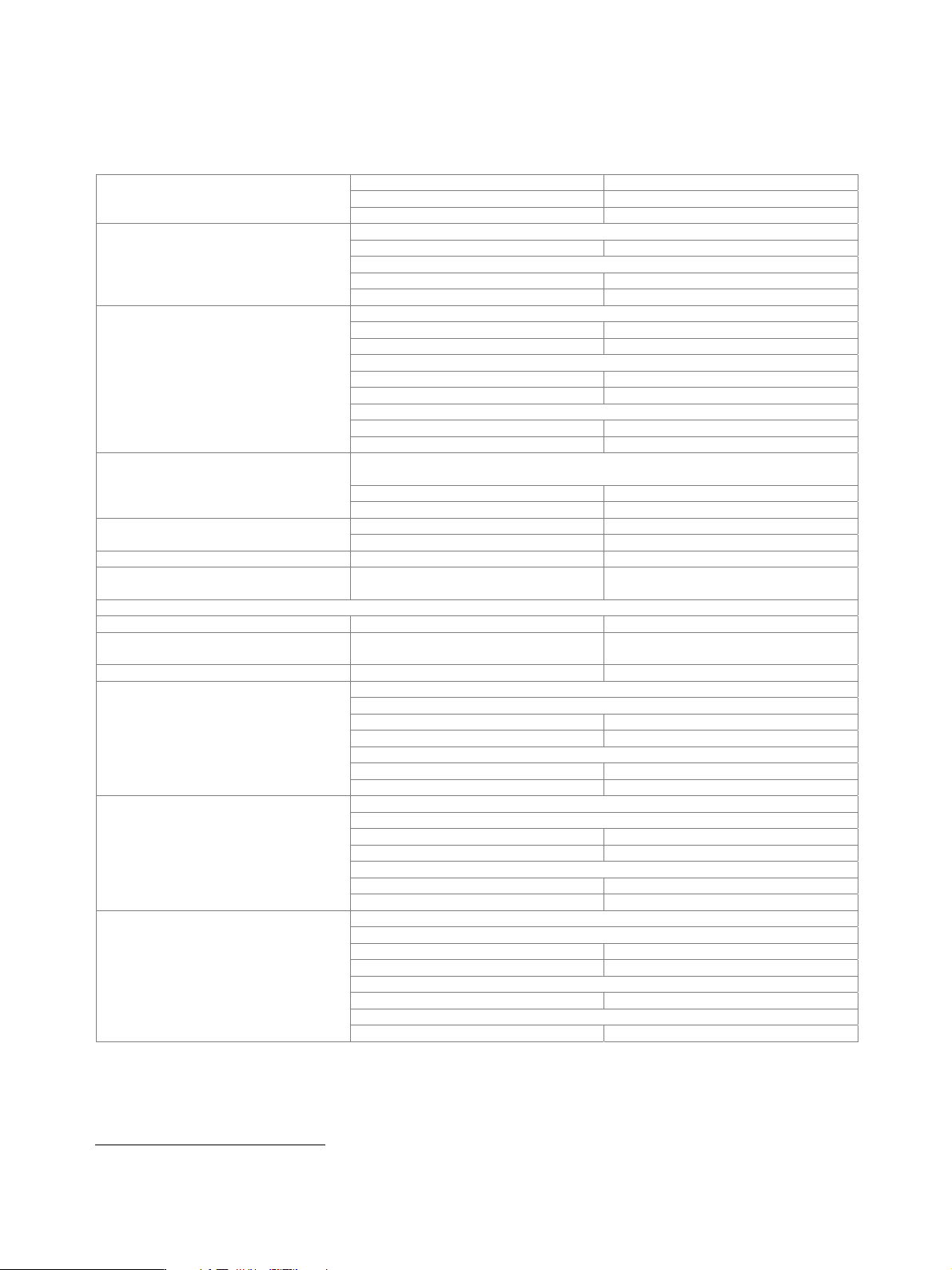
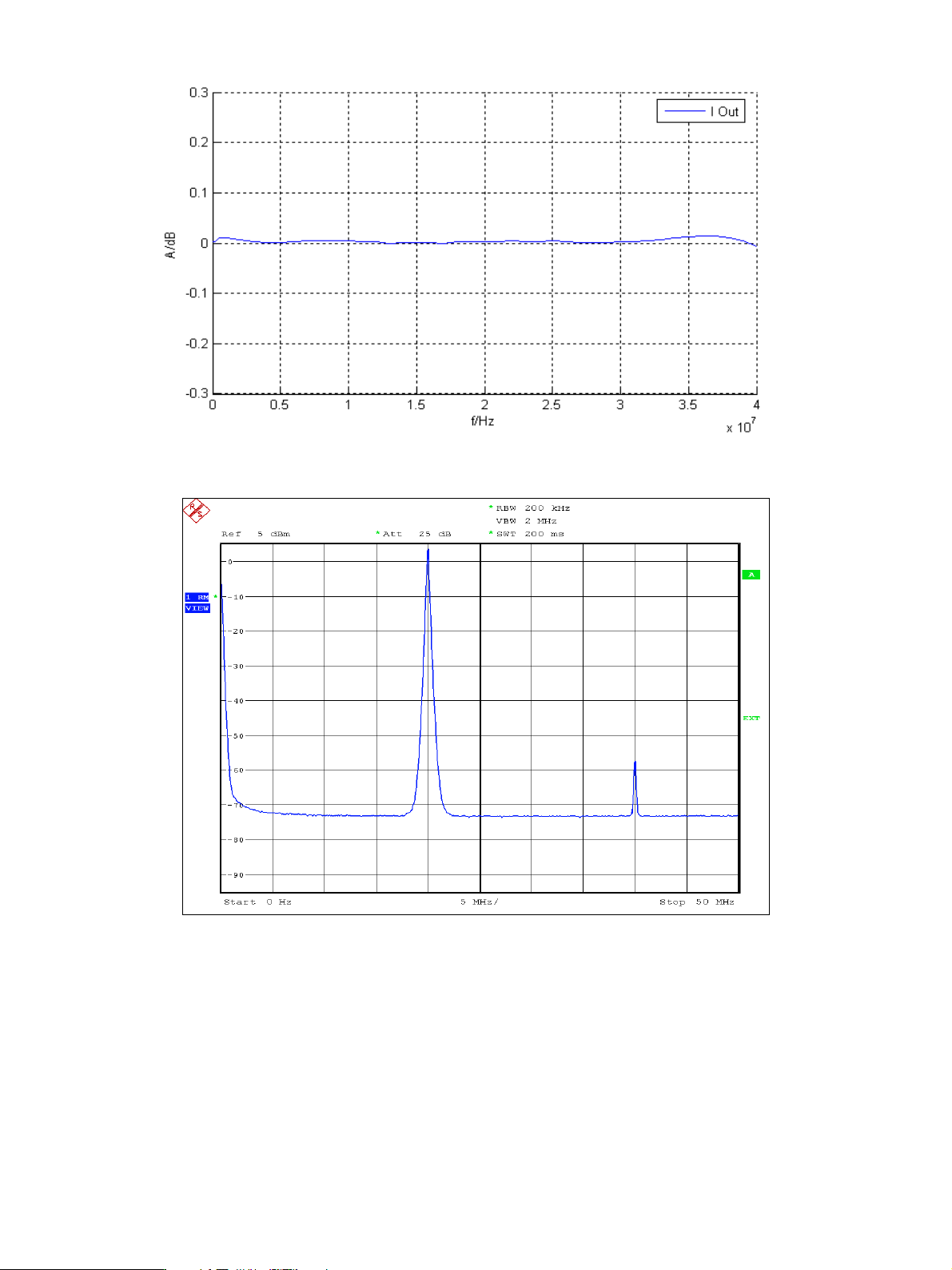
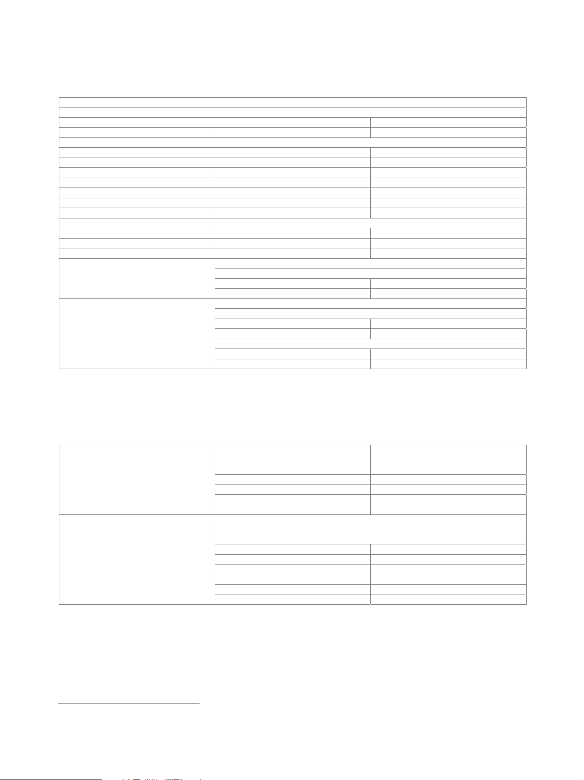
Version 08.00, Januar y 2012 20 Rohde & Schwarz R&S ® SMU200A Vector Signal Generator Measured frequency response of I/Q outputs. Measured SFDR of I/Q outputs.
Version 08.00, January 2012
Rohde & Schwarz R&S
®
SMU200A Vector Signal Generator 19
Internal baseband I/Q (with R&S
®
SMU-B13 option)
The R&S
®
SMU-B13 option converts the internal digital baseband signals of the R&S
®
SMU-B9/-B10/-B11 into analog signals for driving
the I/Q modulator. It also generates the analog I/Q output signals. One or two R&S
®
SMU-B13 can be installed.
The first R&S
®
SMU-B13 drives RF path A, the second RF path B. The I/Q output signals are available either for path A or B.
data rate 100 MHz
resolution 16 bit
D/A converter
sample rate 400 MHz (internal interpolation × 4)
with amplitude, group delay and S
i
correction
bandwidth, roll-off to −0.1 dB 40 MHz
D/A converter interpolation spectra
up to 10 MHz < −80 dBc
Aliasing filter
up to 40 MHz <
−73 dBc
carrier leakage
setting range −10 % to +10 %
resolution 0.01 %
I ≠ Q (imbalance)
setting range −1 dB to +1 dB
resolution 0.001 dB
quadrature offset
setting range −10° to +10°
I/Q impairment
resolution 0.01°
f > 100 MHz, –20 dBm level 10 dBm, I/Q wideband: on, optimize internal I/Q
impairments for RF output: on, optimization mode: high quality
up to 10 MHz < 0.5 dB, 0.1 dB (typ.)
RF frequency response for entire
instrument in modulation bandwidth
up to 40 MHz < 2.0 dB, 0.3 dB (typ.)
up to 10 MHz > 50 dB, 56 dB (typ.) Suppression of image sideband for entire
instrument in modulation bandwidth
3
up to 40 MHz > 40 dB, 50 dB (typ.)
Carrier leakage
3
referenced to full-scale input < −55 dBc, < −65 dBc (typ.)
Additional level uncertainty referenced to
CW
measured at 0 dBm with 16QAM, root
cosine filter,
α = 0.5, 10 kHz symbol rate
< 0.2 dB
I/Q outputs
Output impedance 50
Output voltage EMF (output voltage depends on set
modulation signal)
1 V (V
p
)
Offset EMF < 1 mV
at R
L
= 50
magnitude
up to 10 MHz 0.02 dB (typ.)
up to 40 MHz 0.03 dB (typ.)
nonlinear phase
up to 10 MHz 0.1° (typ.)
Frequency response
4
up to 30 MHz 0.2° (typ.)
at R
L
= 50
magnitude
up to 10 MHz 0.01 dB (typ.)
up to 40 MHz 0.02 dB (typ.)
nonlinear phase
up to 10 MHz 0.1° (typ.)
I/Q balance
4
up to 30 MHz 0.2° (typ.)
at R
L
= 50
SFDR (sine)
up to 2 MHz > 70 dB
up to 20 MHz 60 dB (typ.)
phase noise
10 MHz sine wave at 20 kHz offset −150 dBc (typ.)
wideband noise
Spectral purity
10 MHz sine wave at 1 MHz offset
−155 dBc (typ.)
4
Optimize internal I/Q impairments for RF output switched off.
Version 08.00, January 2012
20 Rohde & Schwarz
R&S
®
SMU200A Vector Signal Generator
Measured frequency response of I/Q outputs.
Measured SFDR of I/Q outputs.
Version 08.00, January 2012
Rohde & Schwarz R&S
®
SMU200A Vector Signal Generator 21
Differential I/Q output (R&S
®
SMU-B16 option)
One R&S
®
SMU-B16 option can be installed; the I/Q output signals are available either for path A or B.
This option is not compatible with rear-panel outputs (R&S
®
SMU-B81 and R&S
®
SMU-B82 options).
Additional specifications for I/Q outputs with R&S
®
SMU-B16 option
Output impedance
Single-ended 50
Differential 100
Output voltage output voltage depends on set modulation signal
Single-ended EMF 0.02 V to 2 V (V
p
)
Resolution 1 mV
Differential EMF 0.04 V to 4 V (V
pp
)
Resolution 2 mV
Bias voltage (single-ended and differential) EMF –3.6 V to +3.6 V
Resolution 2 mV
Uncertainty 1 % + 4 mV
Offset voltage
Differential EMF –300 mV to +300 mV
Resolution 0.2 mV
Uncertainty 1 % + 0.1 % × bias voltage + 1 mV
at R
L
= 50 , output voltage > 0.5 V (V
p
)
magnitude
up to 10 MHz < 0.2 dB, 0.05 dB (typ.)
Differential signal balance
up to 40 MHz 0.2 dB (typ.)
at R
L
= 50 , output voltage > 0.5 V
(V
p
)
magnitude
up to 10 MHz 0.02 dB (typ.)
up to 40 MHz 0.03 dB (typ.)
nonlinear phase
up to 10 MHz 0.1° (typ.)
Frequency response
5
up to 30 MHz 0.2° (typ.)
Digital baseband output (R&S
®
SMU-B18 option)
The R&S
®
SMU-B18 option makes digital I/Q signals available on the rear panel of the instrument. The digital I/Q output can be used
for the lossless connection of the R&S
®
SMU200A to the digital I/Q input of other Rohde & Schwarz instruments (e.g. R&S
®
AMU200A
baseband signal generator and fading simulator). One R&S
®
SMU-B18 can be installed.
standard
in line with Rohde & Schwarz TVR290,
I/Q data and control signals, data and
interface clock
level LVDS
connector 26-pin MDR
Interface
data rate 30 MHz to 100 MHz with 1 MHz resolution,
81.6 MHz
With source ‘user-defined’, the sample rate must be entered via the parameter ‘sample
rate’, no I/Q data clock being necessary. With source ‘digital I/Q out’ or ‘digital I/Q in’,
the sample rate will be estimated on the basis of the applied I/Q data clock.
source user-defined, digital I/Q out, digital I/Q in
sample rate 400 Hz to 100 MHz
max. sample rate limited by actual
interface data rate
resolution (user-defined) 0.001 Hz
I/Q sample rate
frequency uncertainty (user-defined) < 5 × 10
−
14
5
Optimize internal I/Q impairments for RF output switched off.