SMU_dat-sw-en.pdf - 第40页
Version 08.00, Januar y 2012 40 Rohde & Schwarz R&S ® SMU200A Vector Signal Generator 4x2 MIMO Number of signal paths with two R&S ® SMU200A, both with R&S ® SMU-B14 and R&S ® SMU-B15; external signal…
Version 08.00, January 2012
Rohde & Schwarz R&S
®
SMU200A Vector Signal Generator 39
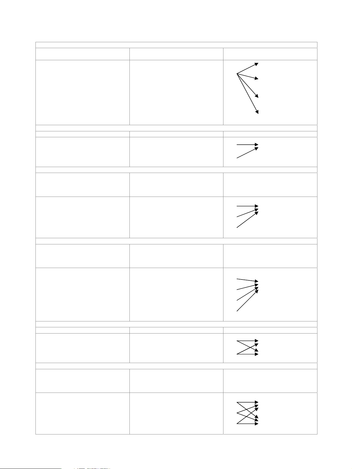
1x4 MIMO
Number of signal paths with two R&S
®
SMU200A, both with
R&S
®
SMU-B14 and R&S
®
SMU-B15
4
Signal routing 1x4 MIMO, simulating fading channels
between one TX and four RX antennas
A
A
B
C
D
2x1 MIMO
Number of signal paths with R&S
®
SMU-B14 and R&S
®
SMU-B15 2
Signal routing 2x1 MIMO, simulating fading channels
between two TX and one RX antennas
A A
B
3x1 MIMO
Number of signal paths with two R&S
®
SMU200A, both with
R&S
®
SMU-B14 and R&S
®
SMU-B15;
external signal combiner required
(either baseband or RF combiner)
3
Signal routing 3x1 MIMO, simulating fading channels
between three TX and one RX antennas
A A
B
C
4x1 MIMO
Number of signal paths with two R&S
®
SMU200A, both with
R&S
®
SMU-B14 and R&S
®
SMU-B15;
external signal combiner required
(either baseband or RF combiner)
4
Signal routing 4x1 MIMO, simulating fading channels
between four TX and one RX antennas
A
A
B
C
D
2x2 MIMO
Number of signal paths with R&S
®
SMU-B14 and R&S
®
SMU-B15 4
Signal routing 2x2 MIMO, simulating fading channels
between two TX and two RX antennas
A A
B B
3x2 MIMO
Number of signal paths with two R&S
®
SMU200A, both with
R&S
®
SMU-B14 and R&S
®
SMU-B15;
external signal combiner required
(either baseband or RF combiner)
6
Signal routing 3x2 MIMO, simulating fading channels
between three TX and two RX antennas
A A
B
C B
Version 08.00, January 2012
40 Rohde & Schwarz
R&S
®
SMU200A Vector Signal Generator
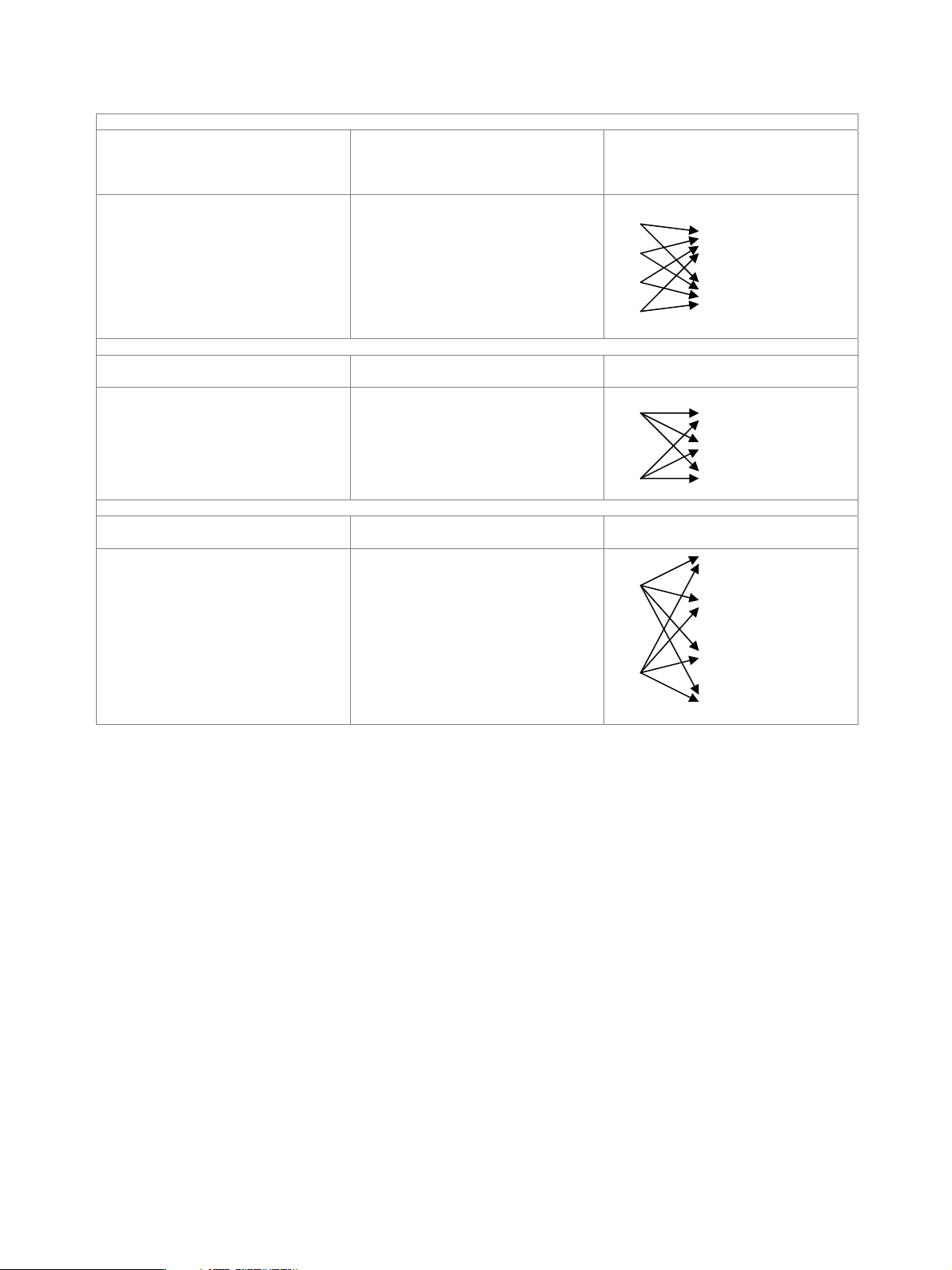
4x2 MIMO
Number of signal paths with two R&S
®
SMU200A, both with
R&S
®
SMU-B14 and R&S
®
SMU-B15;
external signal combiner required
(either baseband or RF combiner)
8
Signal routing 4x2 MIMO, simulating fading channels
between four TX and two RX antennas
A
B A
C B
D
2x3 MIMO
Number of signal paths with two R&S
®
SMU200A, both with
R&S
®
SMU-B14 and R&S
®
SMU-B15
6
Signal routing 2x3 MIMO, simulating fading channels
between two TX and three RX antennas
A A
B
B C
2x4 MIMO
Number of signal paths with two R&S
®
SMU200A, both with
R&S
®
SMU-B14 and R&S
®
SMU-B15
8
Signal routing 2x4 MIMO, simulating fading channels
between two TX and four RX antennas
A
A
B
C
B
D

Version 08.00, January 2012
Rohde & Schwarz R&S
®
SMU200A Vector Signal Generator 41
Dynamic scenario simulation (R&S
®
SMU-K77 option)
At least one R&S
®
SMU-B14 fading simulator must be installed. If both the R&S
®
SMU-B14 and the R&S
®
SMU-B15 are installed (signal
paths A and B), dynamic scenario simulation can be used either on signal path A or B with one R&S
®
SMU-K77 option. For dynamic
scenario simulation to be used on signal paths A and B simultaneously, two R&S
®
SMU-K77 must be installed.
Scenarios
ship to ship simulation of the signal transmission from
one object to another, each moving on a
straight line of definable direction
Predefined
tower to aircraft simulation of the signal transmission
between a tower and an aircraft; the
aircraft takes off, flies a circuit and lands
again
User-defined simulation of two moving objects trajectories and type of object (and their
limits) are fully customizable
A trajectory viewer visualizes the generated trajectories and displays the position of the objects in realtime. The display shows an x-y
and x-z view. The viewer is available for both predefined and user-defined scenarios.
Basic figures
System bandwidth 50 MHz
Number of fading paths 1 LOS per signal path
Fading profiles pure Doppler
Delay resolution 0.5 ns
Propagation delay 0 s to 160 s (corresponds to a range
difference of 0 km to 47.967 km)
Minimum position dwell time 0.1 ms
Maximum Doppler frequency shift 3 kHz
Number of simulated objects 2
Import interfaces
Trajectory description file proprietary file format (see manual) waypoints (ENU, geodetic), velocity, time
TPA file proprietary file format (see manual) time, propagation delay, attenuation
Ephemeris file AGI STK file format position (Cartesian), time, velocity
Export interfaces
Ephemeris file AGI STK file format position (Cartesian), time, velocity
Additive white Gaussian noise (AWGN, R&S
®
SMU-K62 option)
At least one R&S
®
SMU-B13 baseband main module must be installed. If two R&S
®
SMU-B13 are installed (paths A and B), AWGN can
be generated either on path A or B with one R&S
®
SMU-K62 option. For AWGN to be generated on paths A and B simultaneously, two
R&S
®
SMU-K62 must be installed.
Addition of an AWGN signal of settable bandwidth and settable C/N ratio or E
b
/N
0
to a wanted signal. If the noise generator is used,
a frequency offset cannot be added to the wanted signal.
distribution density Gaussian, statistical, separate for I and Q
crest factor > 18 dB
Noise
periodicity > 48 h
setting range −30 dB to +30 dB
resolution 0.1 dB
C/N, E
b
/N
0
uncertainty for system bandwidth = symbol
rate, –24 dB < C/N < 30 dB and
crest factor < 12 dB
< 0.1 dB
bandwidth for determining noise power
range 1 kHz to 80 MHz
System bandwidth
resolution 100 Hz