SMU_dat-sw-en.pdf - 第37页
Version 08.00, Januar y 2012 Rohde & Schwarz R&S ® SMU200A Vector Signal Generator 37 Number of fading pat hs, RF bandwidth an d timing resolution With R&S ® SMU-K71 only With R&S ® SMU-B14 Signal paths F…

Version 08.00, January 2012
36 Rohde & Schwarz
R&S
®
SMU200A Vector Signal Generator
Fading and noise
Fading simulator (R&S
®
SMU-B14 option) and fading simulator extension
(R&S
®
SMU-B15 option)
The R&S
®
SMU-B9/-B10/-B11 or R&S
®
SMU-B17 option is required to generate input signals for the fading simulator.
All frequency and time settings are coupled to the internal reference frequency.
with R&S
®
SMU-B14 1 Number of signal paths
with R&S
®
SMU-B14 and R&S
®
SMU-B15 1 or 2
only possible with R&S
®
SMU-B14 and R&S
®
SMU-B15
input both signal paths split or combined
Signal routing
output split, one signal path only or sum of both
signal paths
Number of fading paths depending on options and signal routing, see table on next page
setting range 0 dB to 50 dB
resolution 0.01 dB
Fading path loss
accuracy < 0.01 dB
setting range 0 ms to 2.56 ms
resolution 10 ns
Fading path delay
with R&S
®
SMU-K71 option 0.01 ns
max. 4 per signal path Delay groups
permitted delay differences within one
group
< 40 µs
at f = 1 GHz 0 km/h to 1725 km/h Speed range
accuracy < 0.128 %
setting range 0 Hz to 1600 Hz Doppler frequency
accuracy < 0.1 %
standard auto Restart
with R&S
®
SMU-B9/-B10/-B11 options
installed
auto, internal from baseband A or B,
external
Total insertion loss automatic or user-definable, with clipping
indicator
0 dB to 18 dB
fading paths in signal path A pairwise with fading paths in signal path B
correlation coefficient
setting range 0 % to 100 %
resolution 5 %
correlation phase
setting range 0° to 360°
Correlation
resolution 1°
Fading profiles
Rayleigh pseudo-noise interval > 93 h
frequency ratio (–1 to +1) × current Doppler frequency Pure Doppler
resolution 0.01 × current Doppler frequency
combination of Rayleigh and pure Doppler Rician
power ratio –30 dB to +30 dB
standard deviation 0 dB to 12 dB
resolution 1 dB
Lognormal
local constant at f = 1 GHz 12 m to 200 m
path loss 0 dB to 50 dB
phase 0° to 360°
Static, constant phase
resolution 1°
Version 08.00, January 2012
Rohde & Schwarz R&S
®
SMU200A Vector Signal Generator 37
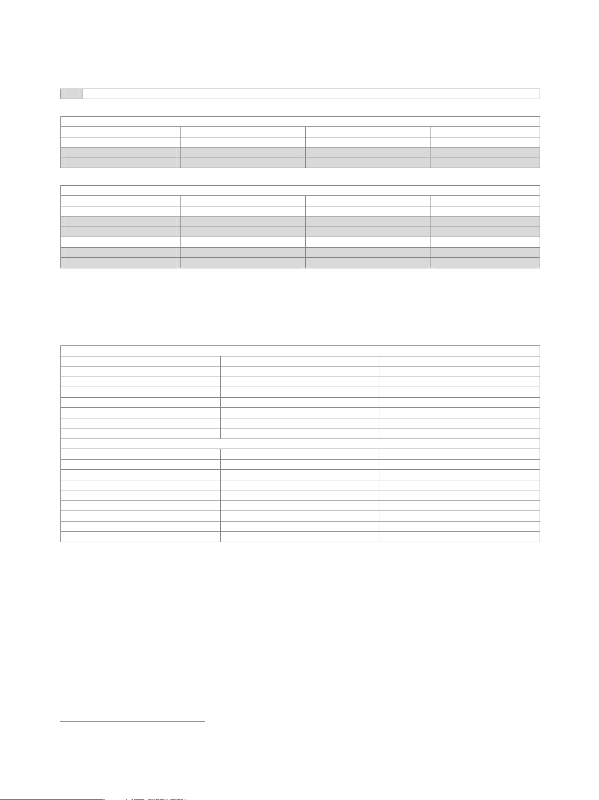
Number of fading paths, RF bandwidth and timing resolution
With R&S
®
SMU-K71 only
With R&S
®
SMU-B14
Signal paths Fading paths RF bandwidth Timing resolution
1 20 80 MHz 10 ns
1 12 30 MHz 0.01 ns
1 8 50 MHz 0.01 ns
With R&S
®
SMU-B14 and R&S
®
SMU-B15
Signal paths Fading paths RF bandwidth Timing resolution
1 40 80 MHz 10 ns
1 24 30 MHz 0.01 ns
1 16 50 MHz 0.01 ns
2 20 80 MHz 10 ns
2 12 30 MHz 0.01 ns
2 8 50 MHz 0.01 ns
Dynamic fading and enhanced resolution (R&S
®
SMU-K71 option)
At least one R&S
®
SMU-B14 fading simulator must be installed. If both the R&S
®
SMU-B14 and the R&S
®
SMU-B15 are installed (signal
paths A and B), dynamic fading and enhanced resolution can be used either on signal path A or B with one R&S
®
SMU-K71 option. For
dynamic fading and enhanced resolution to be used on signal paths A and B simultaneously, two R&S
®
SMU-K71 must be installed.
Moving delay mode
System bandwidth 50 MHz
Number of fading paths 2 per signal path
Fading profiles none
Basic delay in steps of 10 ns 0 ms to 2.56 ms
Delay variation peak to peak 0.3 µs to 40 µs
Variation period peak to peak 10 s to 500 s
Variation speed peak to peak 0 µs/s to 500 µs/s
Delay step size < 10 ps
Birth-death mode
System bandwidth 50 MHz
Number of fading paths 2 per signal path
Fading profiles pure Doppler
Delay range 0 µs to 40 µs
Delay grid 0 µs to 20 µs
16
Positions 3 to 50
16
Hopping dwell 100 ms to 5 s
Start offset separately settable for each signal path 1 ms to 200 ms
Delay resolution 10 ns
16
The maximum delay range of 40 µs cannot be exceeded.
Version 08.00, January 2012
38 Rohde & Schwarz
R&S
®
SMU200A Vector Signal Generator
Extended statistic functions (R&S
®
SMU-K72 option)
At least one R&S
®
SMU-B14 fading simulator must be installed. If both the R&S
®
SMU-B14 and the R&S
®
SMU-B15 are installed (signal
paths A and B), extended statistic functions can be used either on signal path A or B with one R&S
®
SMU-K72 option. For extended
statistic functions to be used on signal paths A and B simultaneously, two R&S
®
SMU-K72 must be installed.
Fading profiles
Gauss I, Gauss II sum of two Gaussian distributions in line with DAB standard
Gauss DAB 1, Gauss DAB 2 Gaussian distribution, shifted in frequency in line with DAB standard
WiMAX™ Doppler rounded Doppler PSD model in line with IEEE 802.16a-03-01
WiMAX™ Rice like WiMAX™ Doppler plus pure Doppler in line with IEEE 802.16a-03-01
SUI1 to SUI6 in line with IEEE 802.16a-03-01 Predefined settings
DAB-RA, DAB-TU, DAB-SFN in line with EN 50248-2001
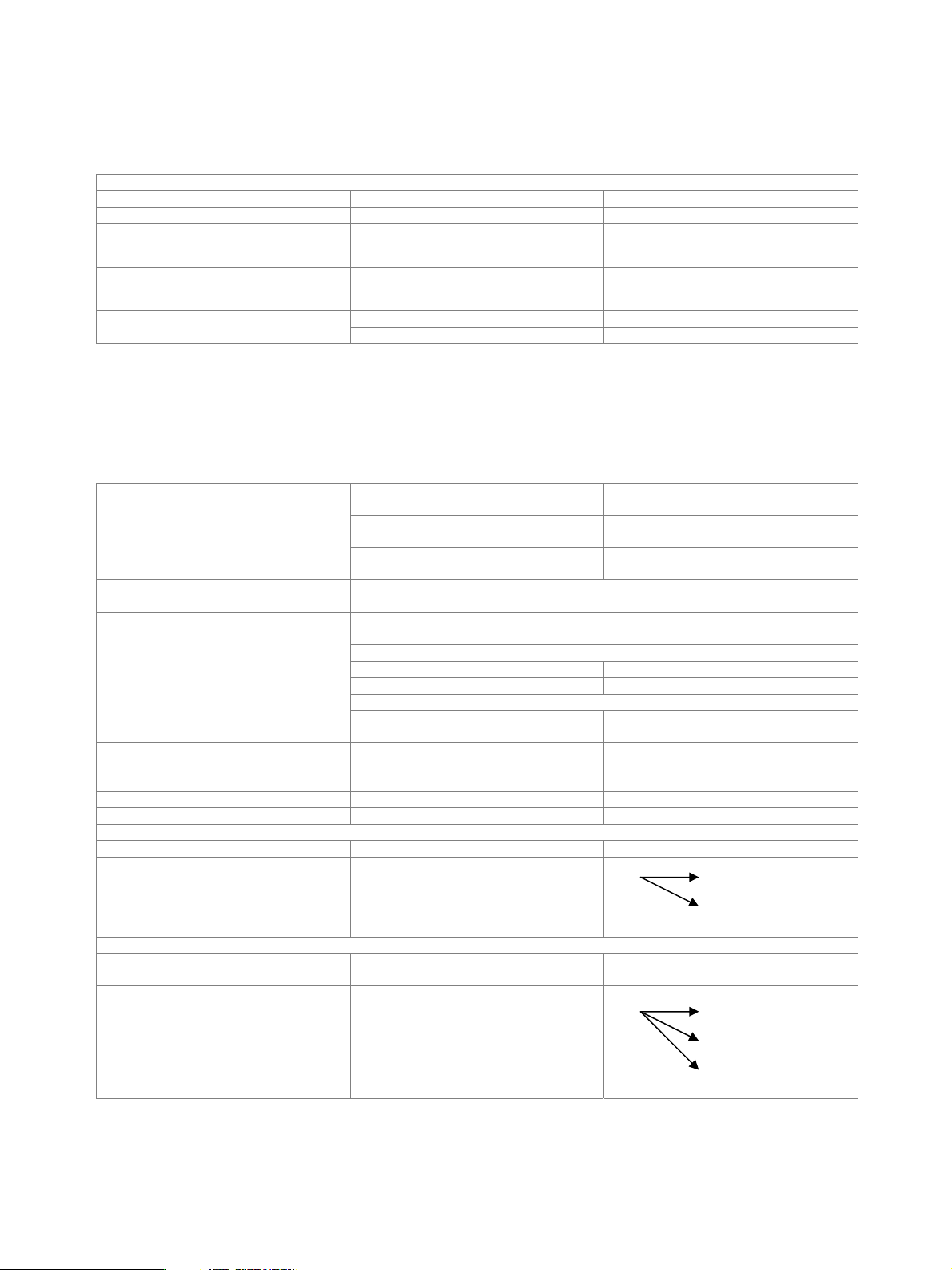
MIMO fading (R&S
®
SMU-K74 option)
The R&S
®
SMU-K74 option allows four fading channels to be simulated as is required for 1x2, 2x1 and 2x2 MIMO receiver tests.
Both the R&S
®
SMU-B14 and the R&S
®
SMU-B15 options must be installed (signal paths A and B) and two baseband sources
(R&S
®
SMU-B9, -B10 or -B11) must be present. By combining two instruments, it is possible to simulate receiver test scenarios for 1x3,
1x4, 2x3, 2x4, 3x1, 4x1, 3x2 and 4x2 MIMO.
standard, 80 MHz RF bandwidth,
10 ns timing resolution
10
with R&S
®
SMU-K71 option, 50 MHz RF
bandwidth, 0.01 ns timing resolution
4
Number of fading paths in each channel
with R&S
®
SMU-K71 option, 30 MHz RF
bandwidth, 0.01 ns timing resolution
6
Steering matrix The steering matrix can be set by setting the diagonal elements of the correlation
matrix.
The correlation between corresponding fading paths of the signal paths can be set in a
correlation matrix. For each fading path index, an individual matrix can be set.
correlation coefficient
setting range 0 % to 100 %
resolution 1 %
correlation phase
setting range 0° to 360°
Correlation
resolution 1°
Correlation matrix setting individually or with Kronecker assumption
(RX and TX antenna correlation with
automatic calculation of matrix)
Matrix representation (real, imaginary) or (magnitude, phase)
Start seed settable
1x2 MIMO
Number of signal paths with R&S
®
SMU-B14 and R&S
®
SMU-B15 2
Signal routing 1x2 MIMO, simulating fading channels
between one TX and two RX antennas
A A
B
1x3 MIMO
Number of signal paths
with two R&S
®
SMU200A, both with
R&S
®
SMU-B14 and R&S
®
SMU-B15
3
Signal routing 1x3 MIMO, simulating fading channels
between one TX and three RX antennas
A A
B
C