00193853-01.pdf - 第18页
Retrofit instructions SIPLACE S-27 HM Long Board Option 10/2004 Edition 18 : Replac e the M6 x 3 5 mm DIN 912 s crew with a scr ew 35 mm lon g and then s crew on the r ub- ber buffers onc e more with th e lifting table p…
Retrofit instructions SIPLACE S-27 HM Long Board Option
10/2004 Edition
17
2.3 Restrictions
– Pass-through height for components on the underside of the PCB = 20 mm
– Minimum PCB width approx. 100 mm
2.4 Conversion
: Switch the placement machine off at the main switch.
2
: Remove the standard lifting table bed.
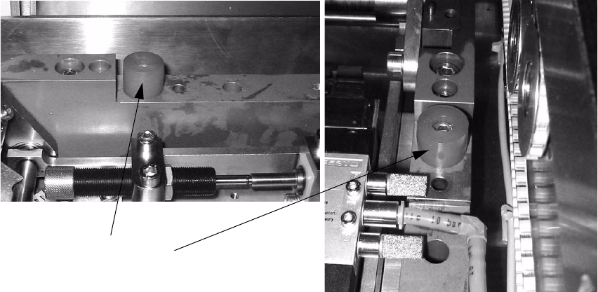
: Unscrew both rubber buffers from the lifting table.
2
2
2
2
2
2
2
2
2
2
2
Rubber buffer
Retrofit instructions SIPLACE S-27 HM Long Board Option
10/2004 Edition
18
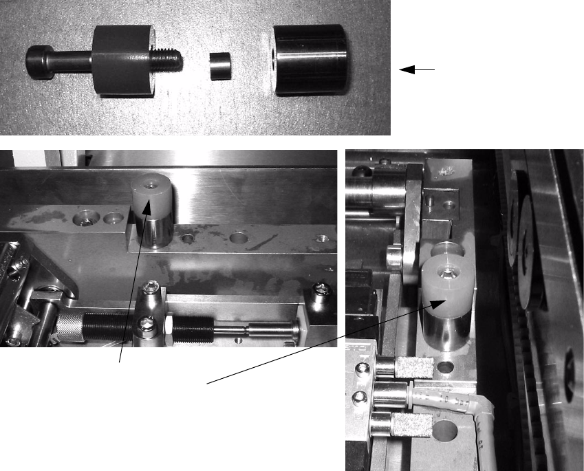
: Replace the M6 x 35 mm DIN 912 screw with a screw 35 mm long and then screw on the rub-
ber buffers once more with the lifting table path limiters fitted (height 20 mm).
2
2
2
2
2
2
2
2
2
2
2
2
35 mm screw with
path limiter
Rubber buffers with
path limiters
Retrofit instructions SIPLACE S-27 HM Long Board Option
10/2004 Edition
19
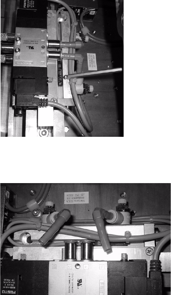
: Mark the current position of the cylinder switch.
2
2
: Detach the air hoses from the cylinder or valve.
This will depressurize the lifting table cylinder and allow you to move the mechanism.
2
2
: With the machine switched on (the LED must be on), adjust the cylinder switch so that it
switches reliably when the lifting table height is 20 mm (height of the rubber buffer).
: Adjust the air regulator at the cylinder of the lifting table for the motion downward, if necessary.
2